I wanted a starwheel tailstock for a long time – and finally got one on a company liquidation. It was not in a good shape, but I like a lot to refurbish this kind of tools.
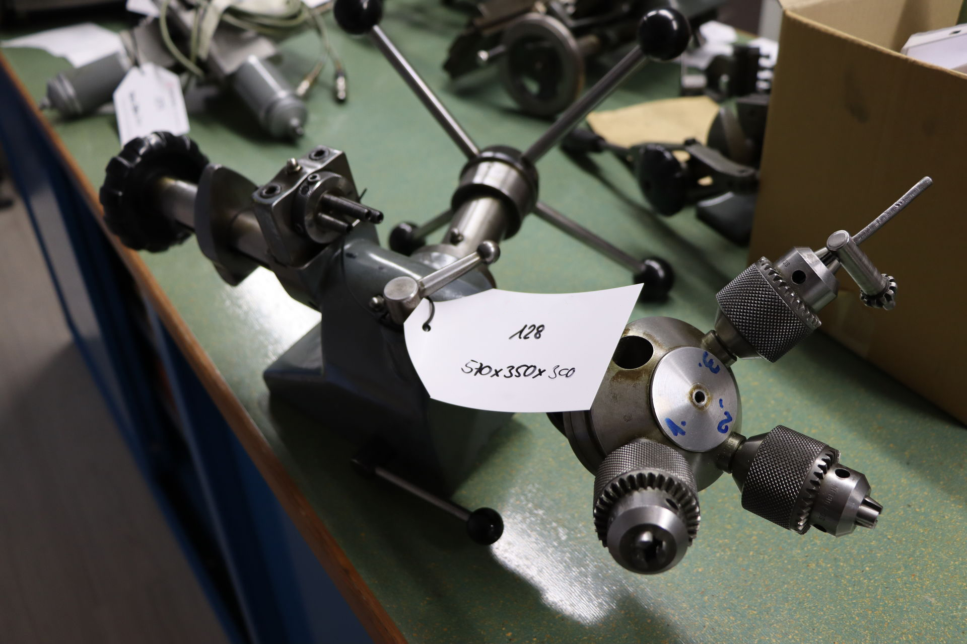
The item how it was presented at the auction
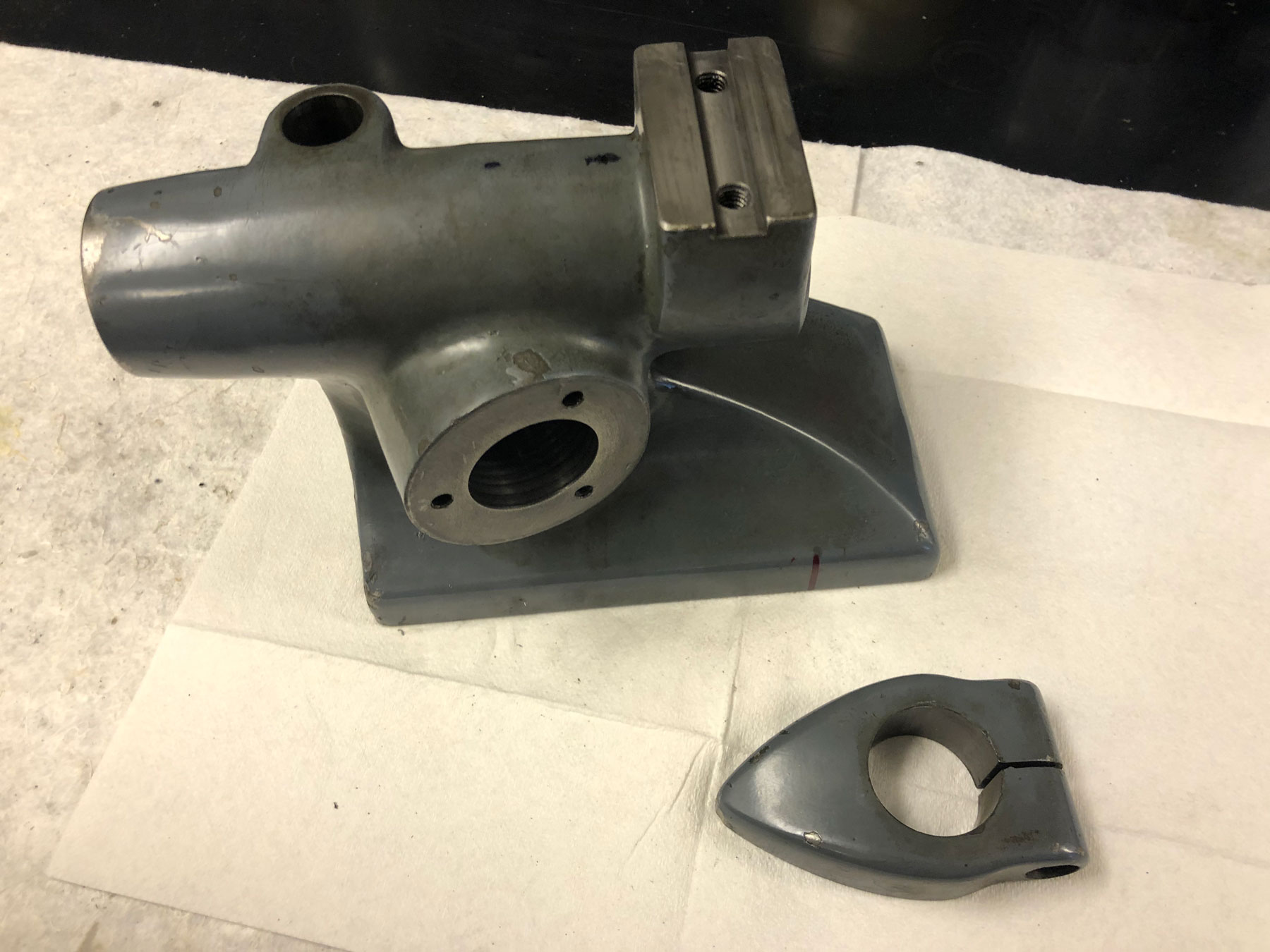
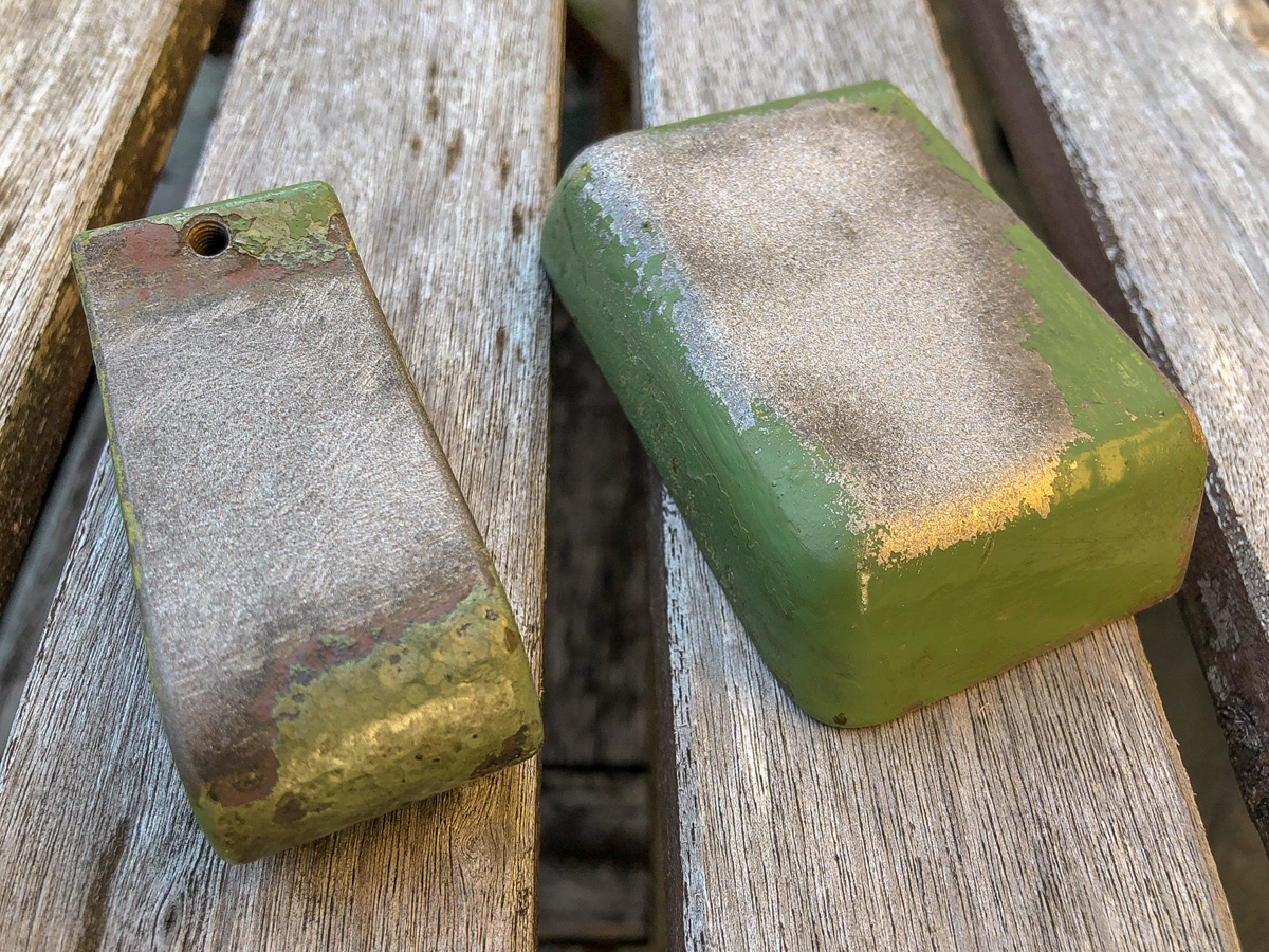
Disassembled parts of the gray tailstock
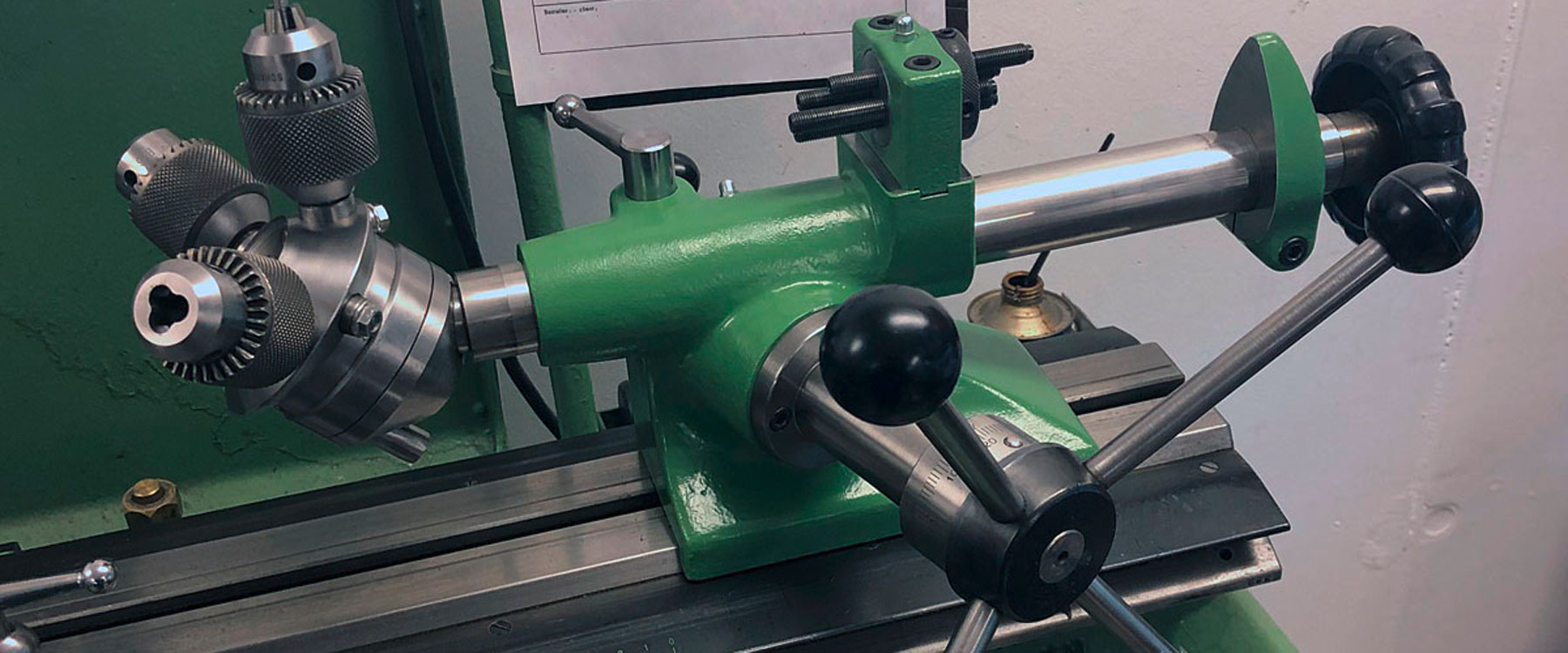
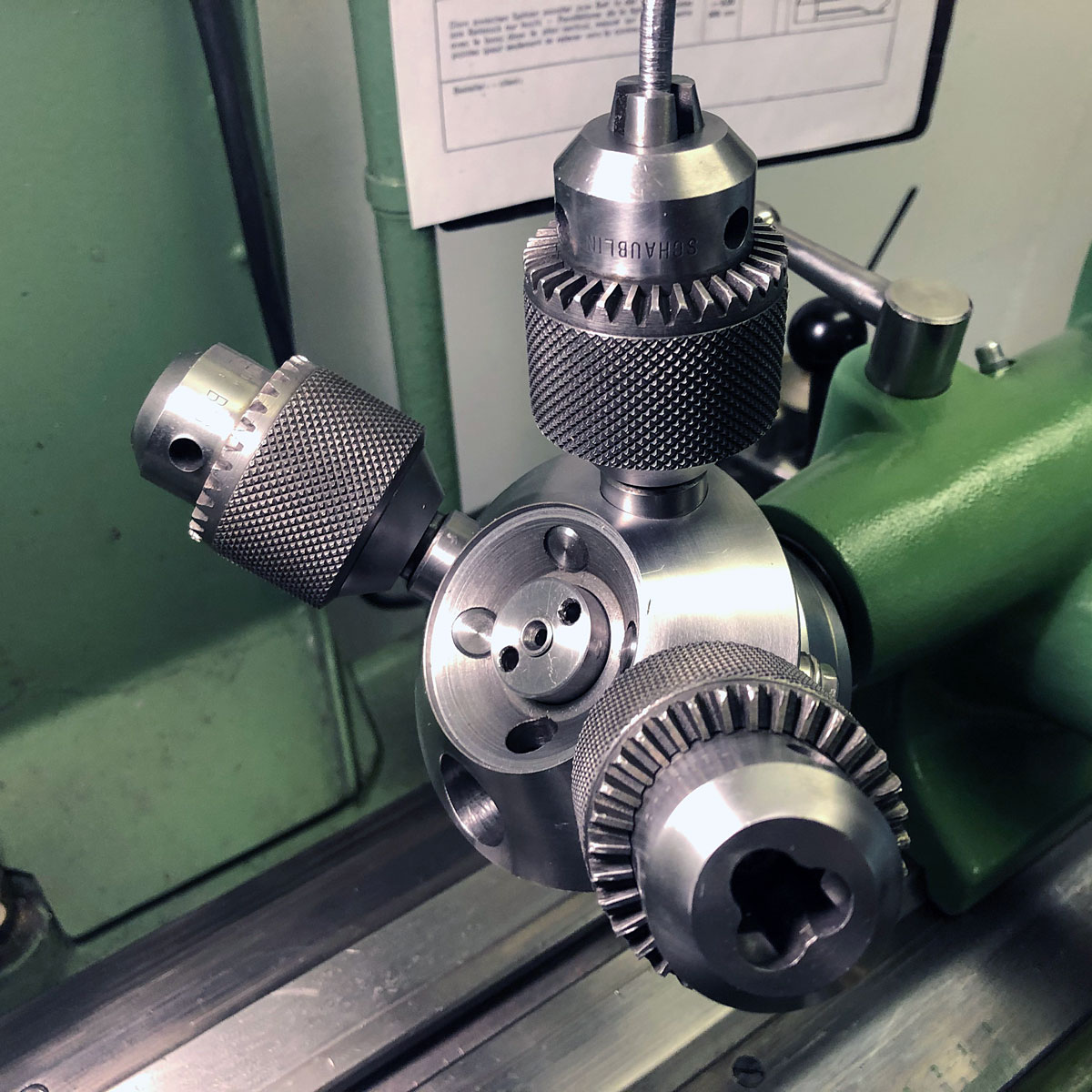
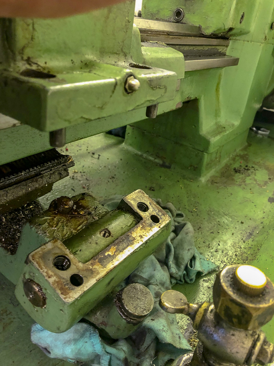
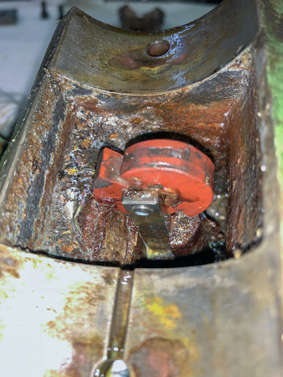
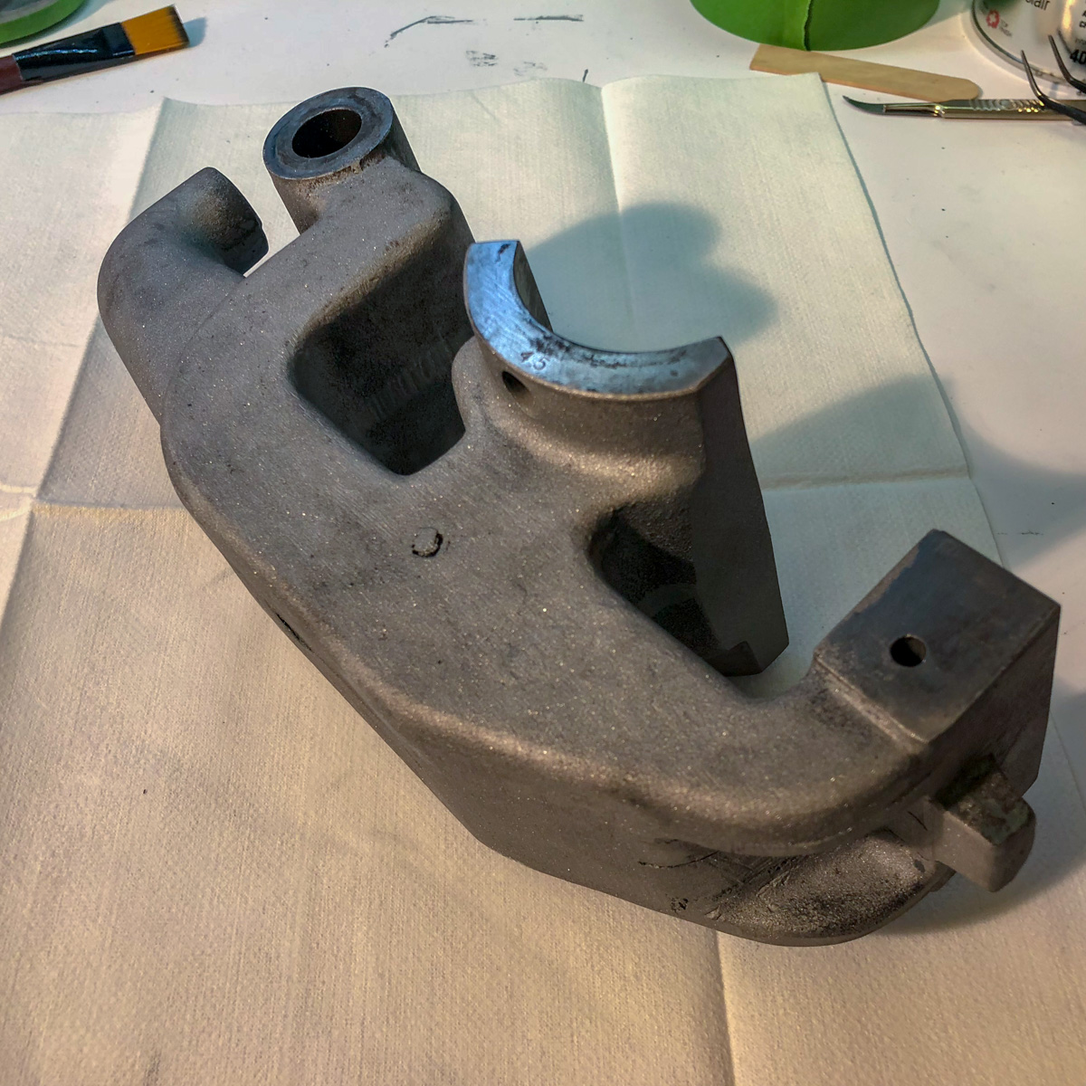
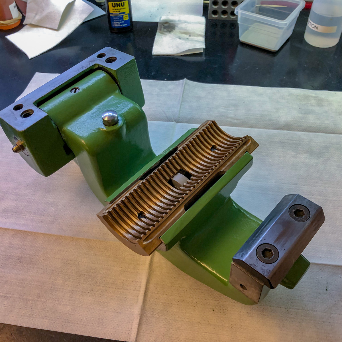
The toolchanger is mounted on a W20-collet and had some problems: it was sloppy and had some broken parts (which I don’t know how they are named officially).
It’s the part where the tool/toolholder is clamped. The clamping force is obtained by thightening the screw on the top of the part. Two of those screws had ruined threads, one was broken off completely! I think this happened to somebody, who didn’t know about the function of this clamp – but I have to admit, that I’ve also never seen this kind of clamping by pushing a rod upwards…
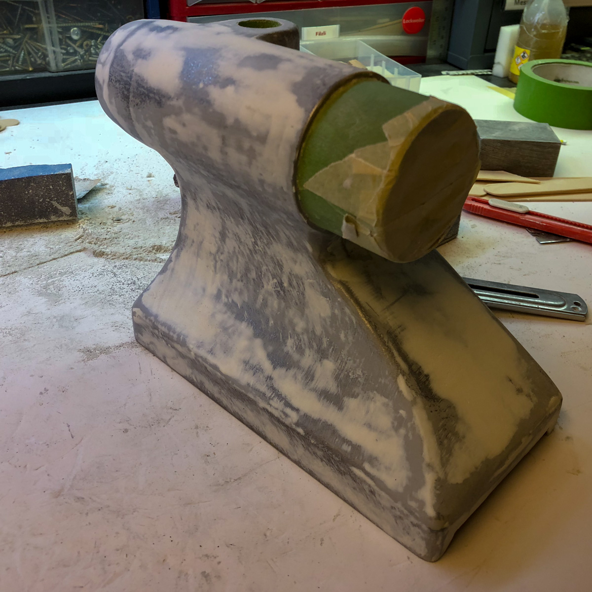
After disassembling and cleaning the whole tool, the same old steps again: sanding off the old paint, priming, filling, sanding and painting again. This time without the indulgence of a sandblaster (really a lot of handwork).
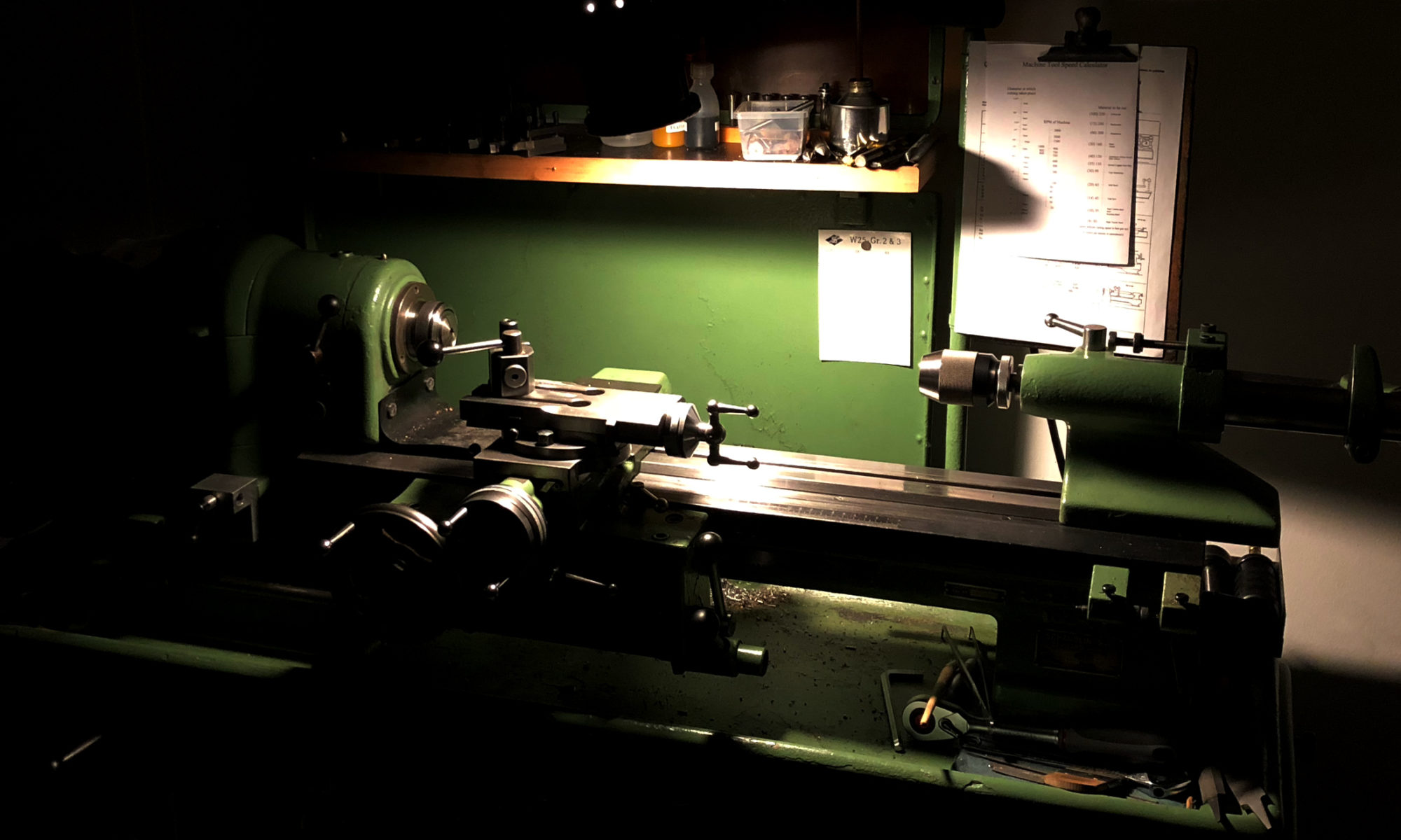
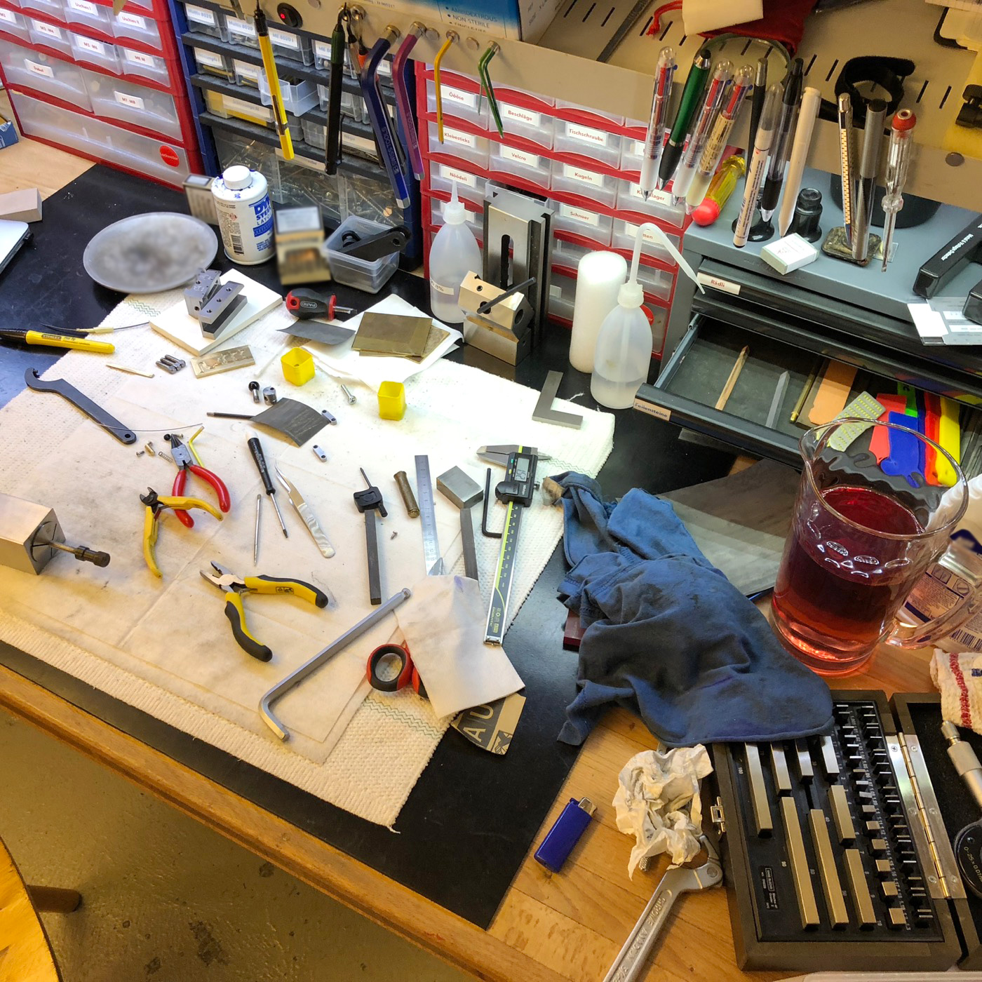
I like to work in a «styled workshop» – funny, isn’t it? 🙂
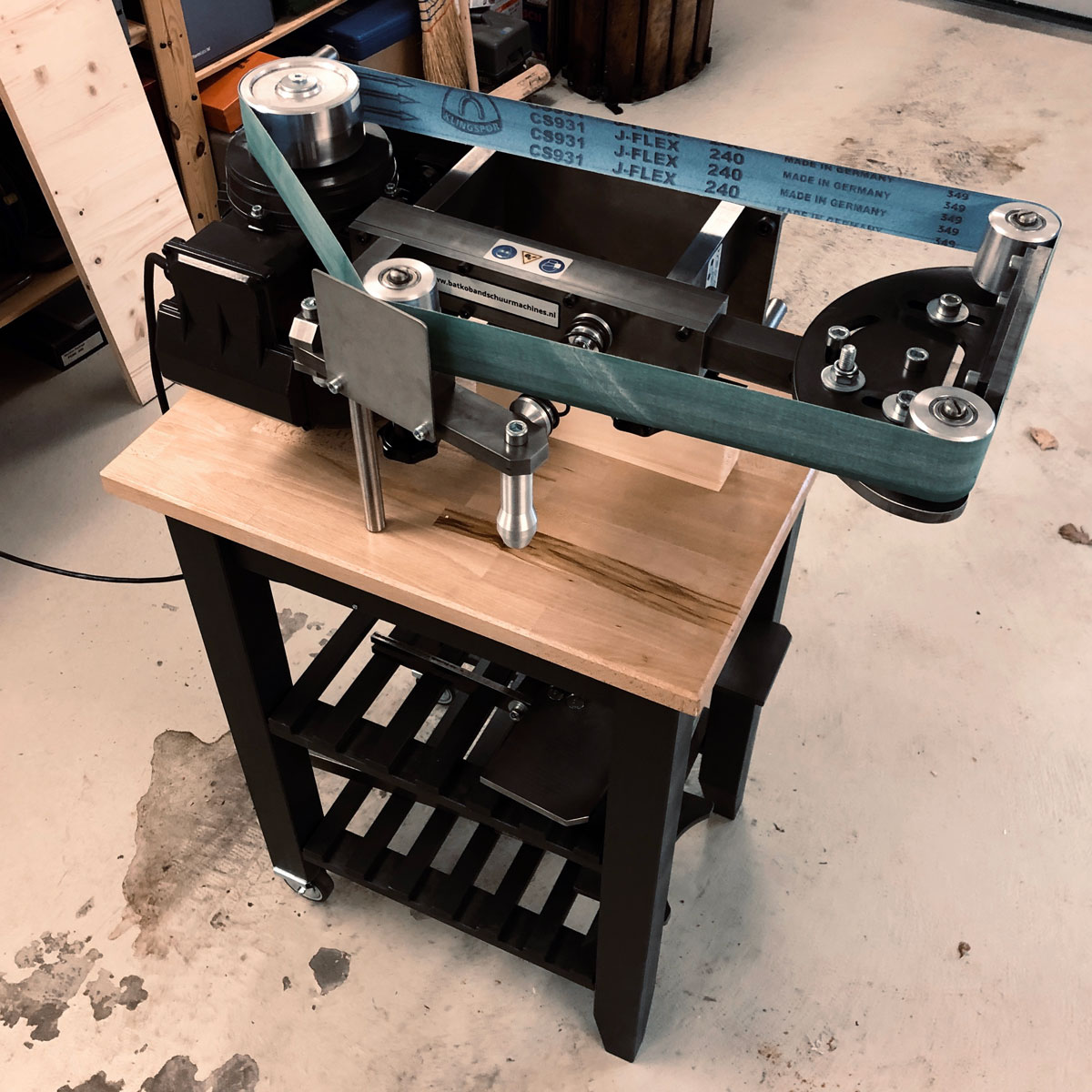
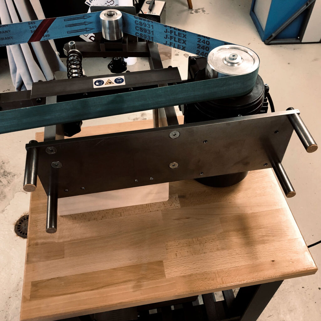
For the new Batko belt grinder a small and mobile surface would ideal. You can place it where you need it, and where the dust won’t bother. Some of my older workbenches are from the IKEA-kitchen-line «Bekväm». They sturdy, stable (some mods required) and as you’ll see: highly customizable. With a touch of paint (bottom in a dark gray and the table varnished with parquet lacquer) a pair of new wheels it will get a irreplacable tool in the workshop.
The Batko belt grinder in vertical and horizontal position
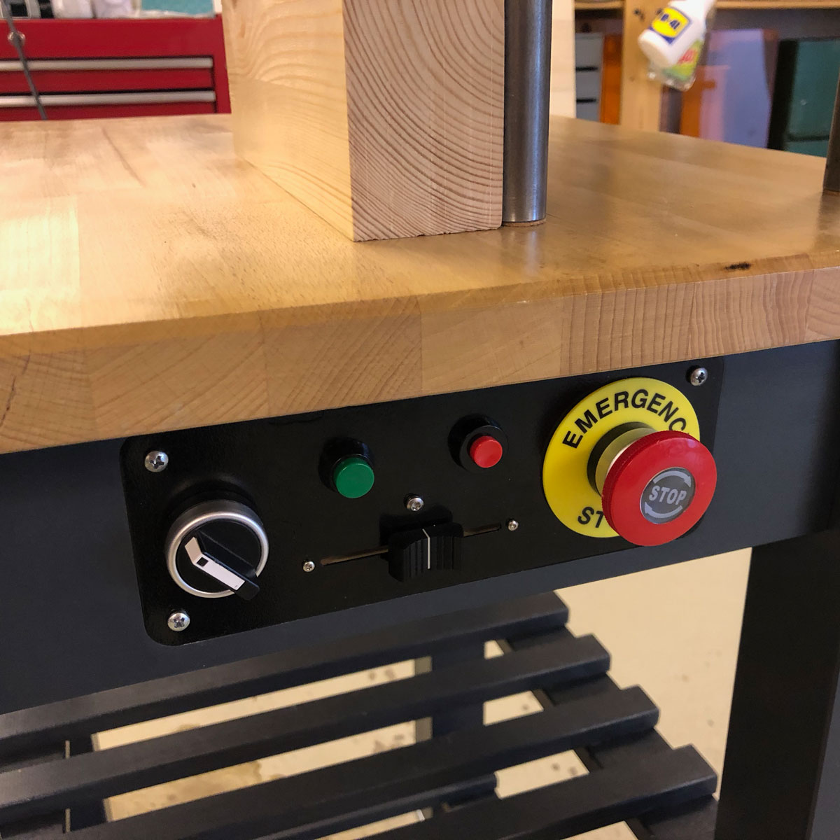
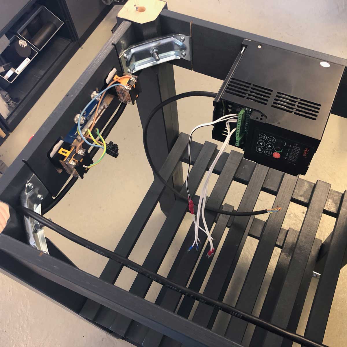
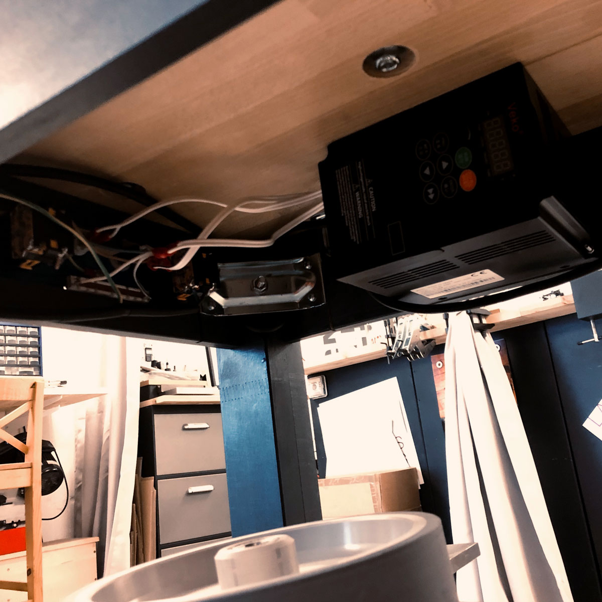
The frequency drive and the control panel were placetdin the bottom part, right below the plate. Luckily, the VFD has just the right width. The panel was cut with the Tormach PCNC440 and inset on the front part. To be honest: the wiring was a little PITA. The manual isn’t a quality product (e.g. resistance not readable) – as in most of these products. Well, but when you get it to work, you really enjoy it even more…
Control panel and the hidden VFD
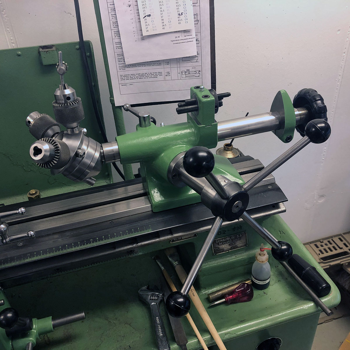
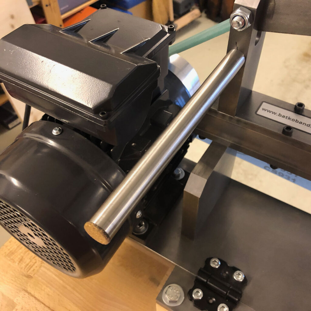
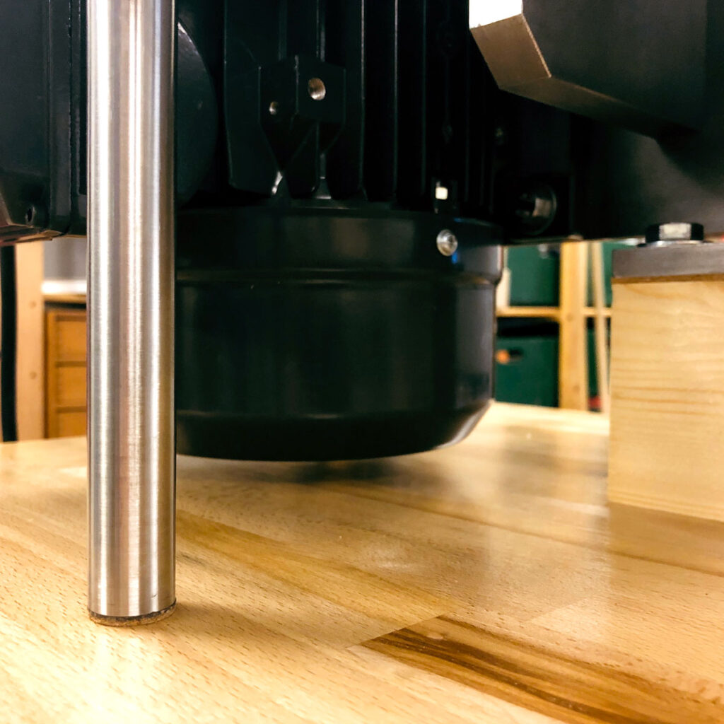
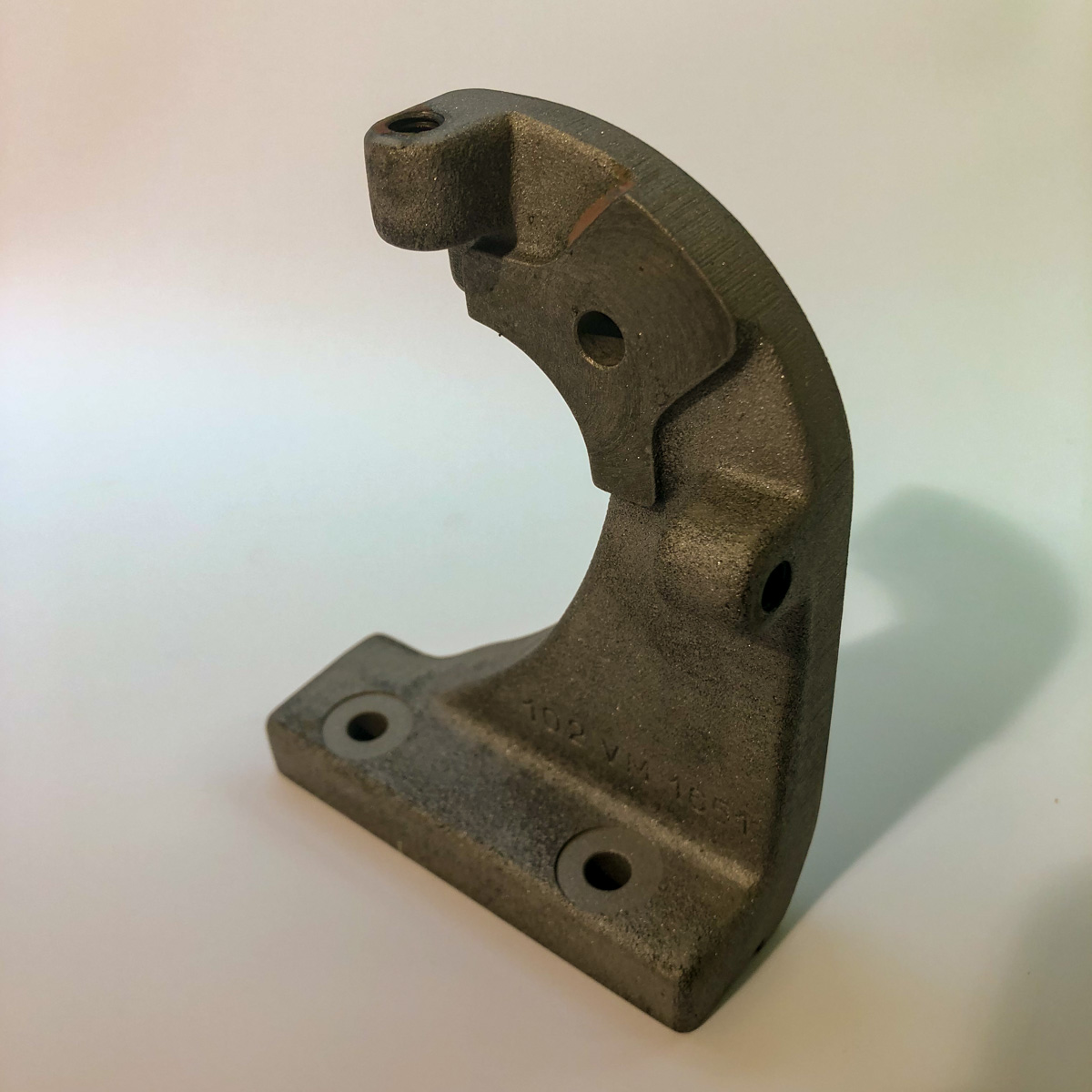
Tilting the machine needs an extra: the motor needs it’s place! So you need to lift the whole machine for about 80 mm. I fixed this with a wooden block and some supports turned on the Schaublin 102VM. The support on the handle needed to be extended – the drilled holes on the base plate (normaly used to fix the machine) were used, to place the standoffs. Aiming not to scratch the plate and stop up vibrations: some cork feets (as attempt).
The image on the right side shows the reason why the machine needs to be lifted a little bit…
Some parts of the Schaublin were overhauled in a way, that doesn’t accomodate my style of work. The parts were overpainted without being taken apart – most of them «freehand» without masking or something alike. Moreover, the wrong paint was used: it began to blob and to sliver apart…
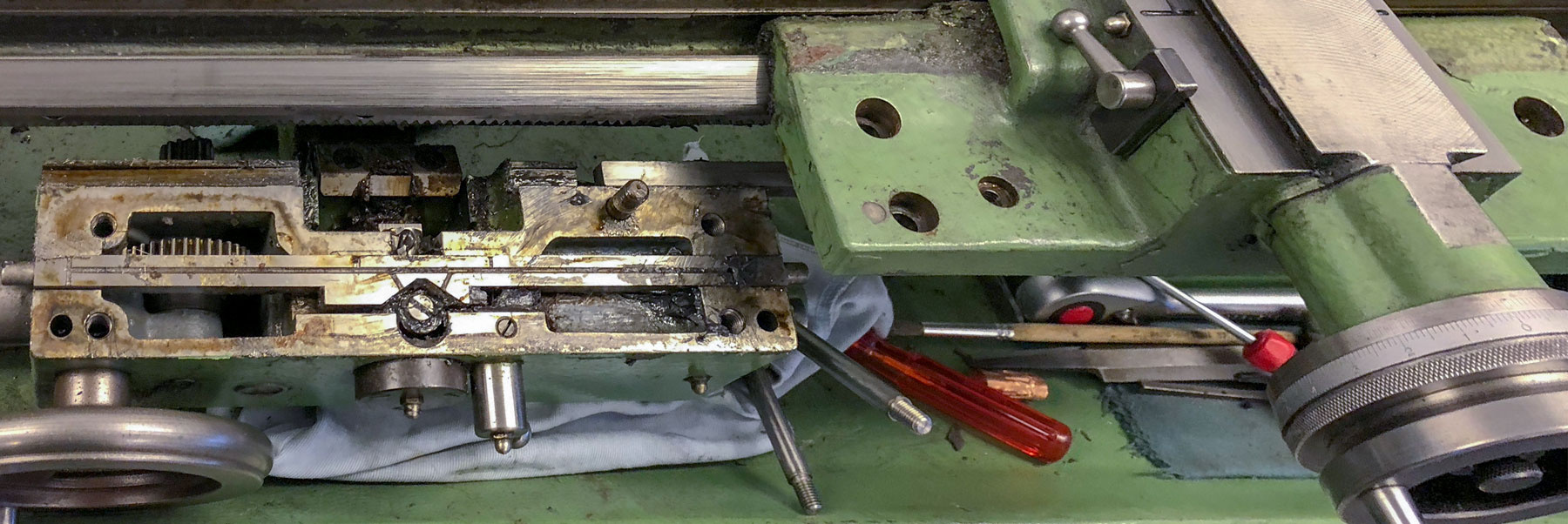
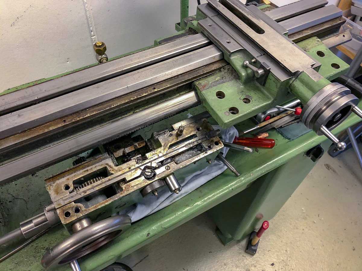
Saddle with cross-slide and bed-guards removed. The ways look ok – I won’t do anything on those (this needs a professional).
The right side of the saddle. The piece on the bottom that looks out a little bit, is on of the two end-stops of the powerfeed.
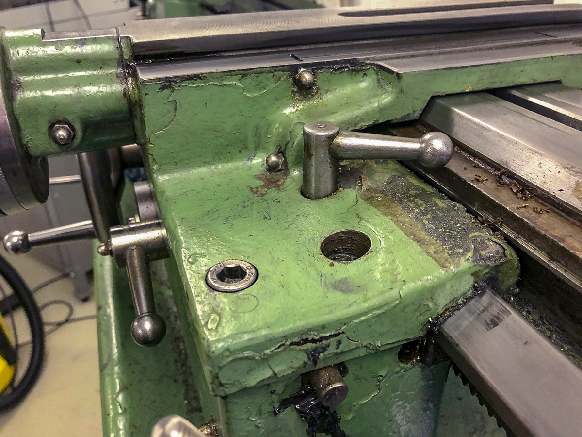
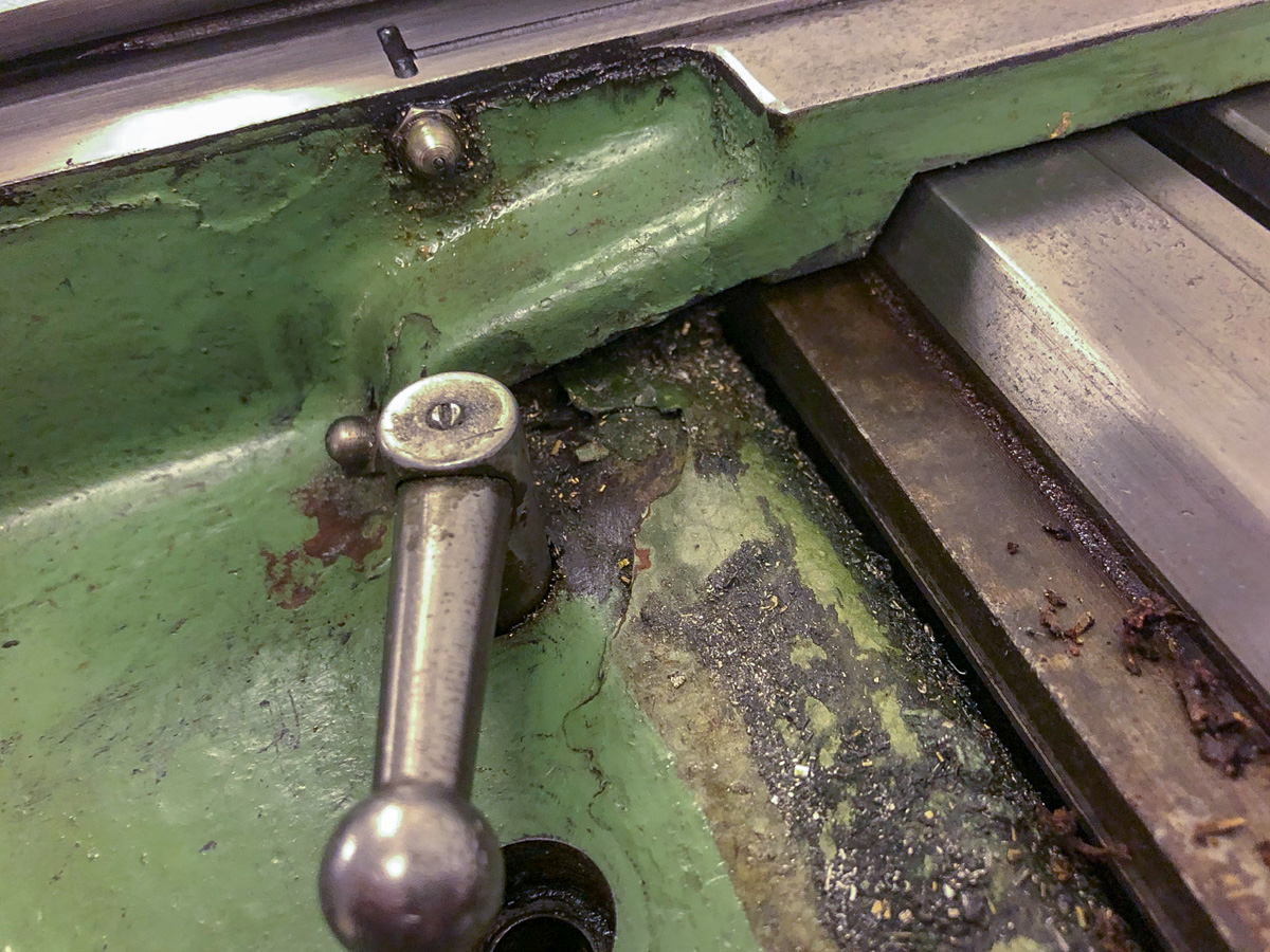
Closer look on the right side. Notice the coatings and the different types of paint.
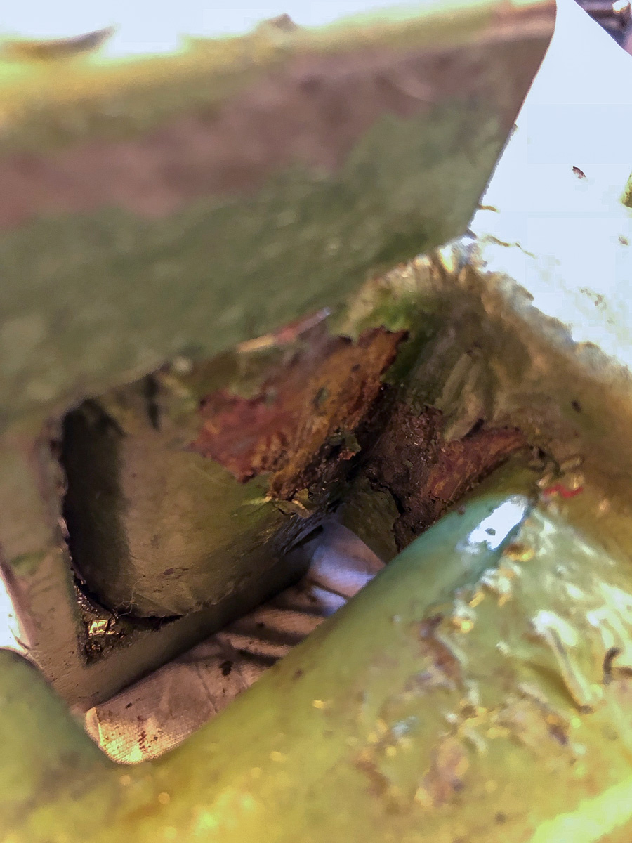
Well… here the wrong type of paint was used. Nothing to say more here.
Dismantling
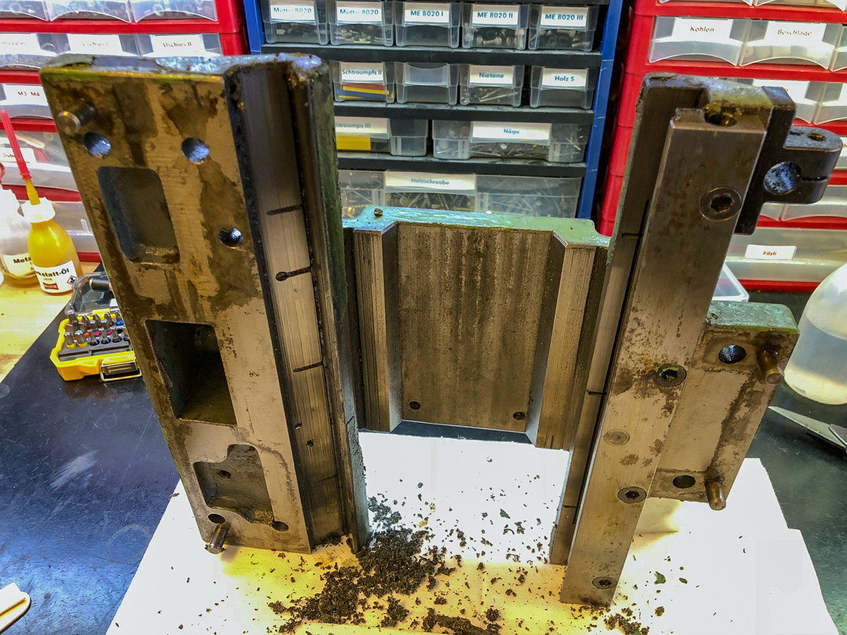
The apron was tricky to disassemble. Probably, this was the first time for years, that someone did that. Perhaps it was even a premiere, that every detailed part was disassembled and cleaned – some parts revealed the original paint, others the «history» behind it.
On this picture, the saddle is separated from the apron. This was a lot of work – those two buddies stucked togheter like two pages of wet paper!
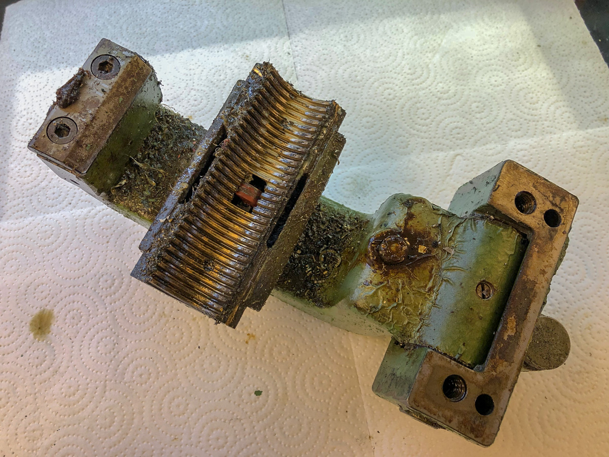
The back side of the combination. On the left: the heavy leadscrew-halfnut, on top the saddle. The cap on the leadscrew-assembly is the filler plug for the leadscrew lubrication.
The leadscrew assembly. The part is hollow and operates as oil reservoir. The leadspindle is lubricated with a disc in the middle of the leadscrew-nut. On of the rare non-metal-parts.
The leadscrew-nut in detail. We’ll see more of this later. Mounted in the middle: the lubricating disc of the 40mm leadscrew.
Cleaning and inspecting
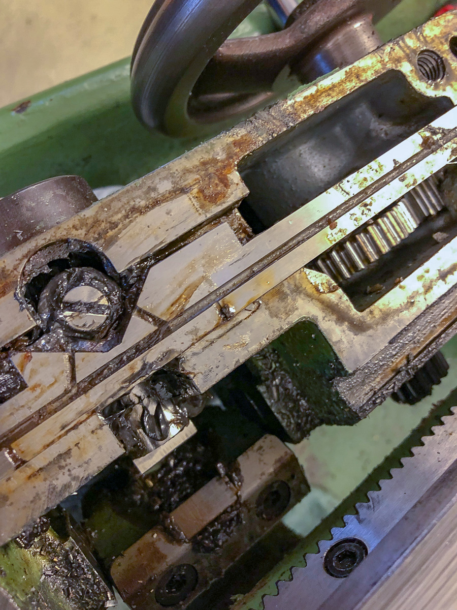
As you will see next, the inside of the machine wasn’t cleaned for years probably. But this mix of oil, grease, chips and dirt comes loose quite easy – yes, it’s a mess though. I’ll address the grease and oil chapter lather.
Top view of the apron’s inside. The rail with the oil grooves functions as end-stop (working on both ends) for the power feed.
The axle which connects the apron-saddle combinations to the leadscrew part
Inside the apron. Notice the pipe in the middle: it’s a oil pipe lubricating the axle on the left picture
Lower side of the saddle. This is a important and delicate part!
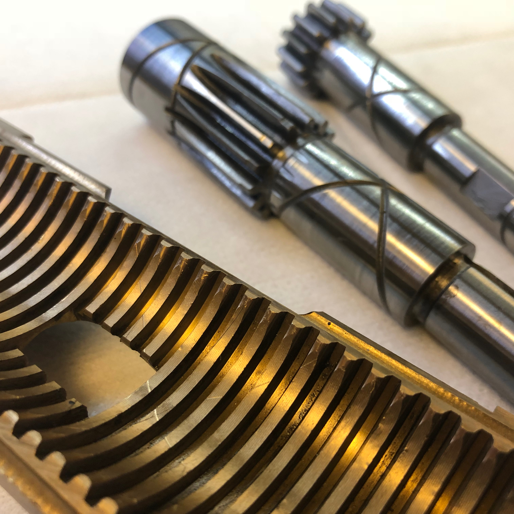
Underneath the mud, a beauty appeared! The craftsmanship of Schaublin is really a joy to have a look at – nothing compared to todays «chineasium machines» (to have AvE mentioned).
I’ll show some parts just to show the high quality and how they are made. After more than 60 years, I’ve found just one piece that really is broken! The remaining parts have wear of course – but nothing to be really concerned about.
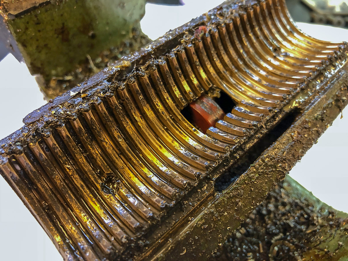
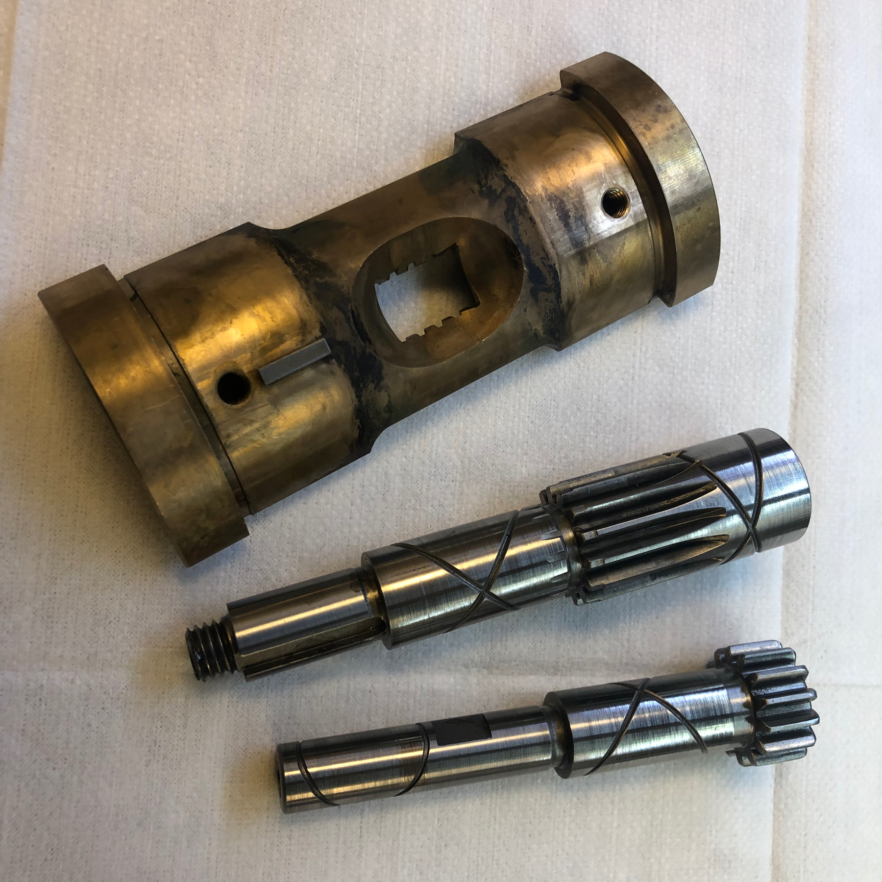
The leadscrew-nut and some axles in detail. The nut shows some wear on the entry and the exit of the thread-grooves.
The backside of the leadscrew nut. in the middle, the cavity for the lubrication disc…
… which was broken! Yeah: one non-metal-part and guess what breaks? Not sure how to fix this yet – the axis sits bombproof.
Here another pic of the sliding axle (the one where the direction of the powerfeed is set). Due to the sliding functionality, this wear is really common.
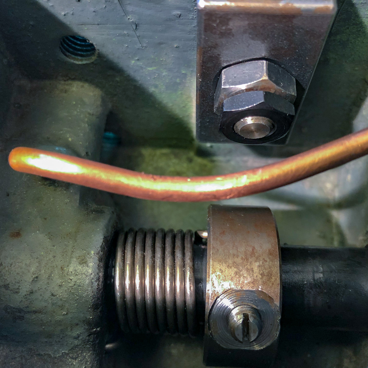
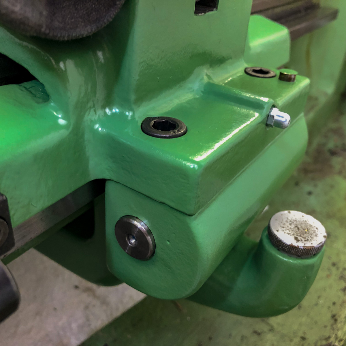
Oil not grease: the nipples
On the same time, Bob Miller is also digging in his Schaublin. Besides also being one of them… well… in his words:
bob_mllr What appear to be grease nipples are not always for grease 😢. Someone thought so though when they lubed the Schaublin 102vm apron.
I used a kind of really fine grease for that – and probably didn’t perish too much. But after degreasing everything and cleaning it really deeply through all oil tubes and oil paths – it’s the right time to switch to an appropriate oil ! Being invited at Schaublin in Bévilard in a few weeks, I’ll get the right one from them.
Preparing for sandblasting
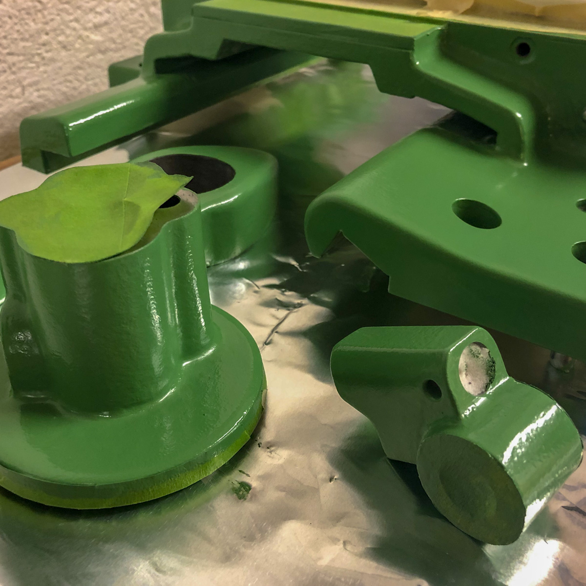
All the parts were cleaned and prepared for sandblasting. This is the first time that I give something to be sandblasted, and right: I’m a little nervous about this. I hope this will be done cautious – I prefer doing some handwork compared to damages that are hard to fix! Here’s what it looks like:
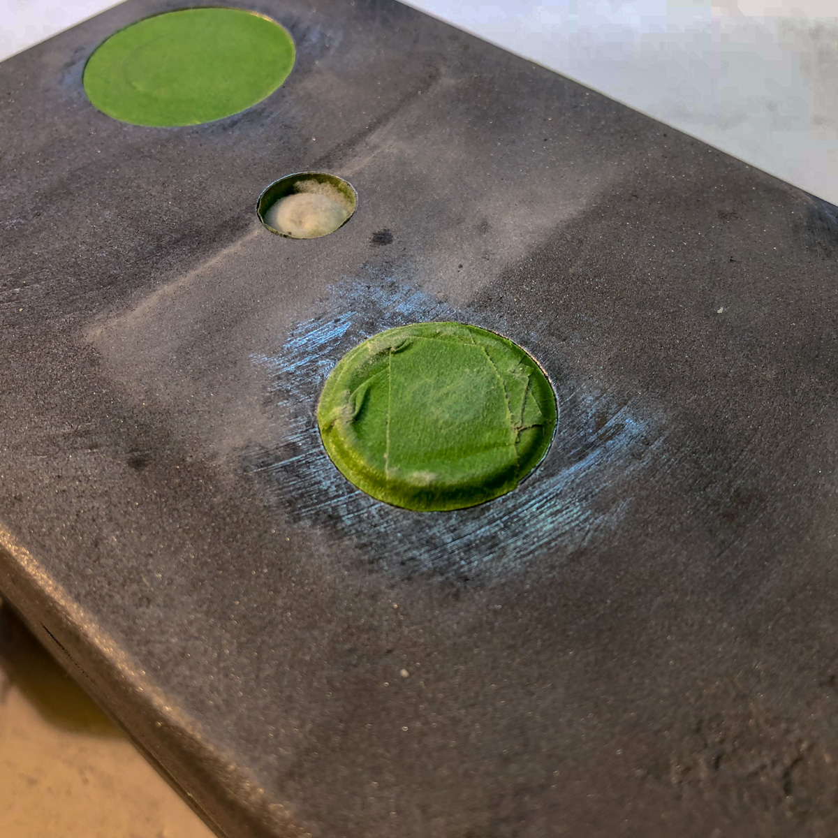
Five different options: ducktape (once or twice), piece on pipe (on the left), piece of scrap rod (on the right), some wooden pieces and some kind of sponge-bob.
We tested the used abrasive material on two uncomplicated pieces. Works fine: all paint is gone!
Back from sandblasting
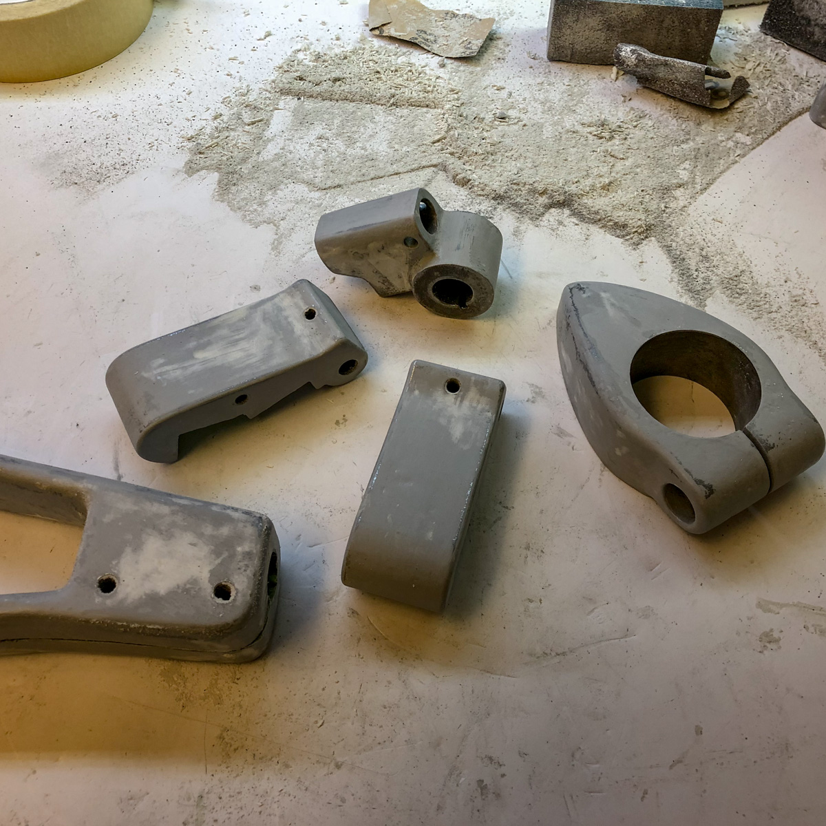
The blaster-master did a really good job: the parts turned out fine. No major parts were damaged! Some dents though, but not on important areas.
The parts turned out nice and clean, no major parts damaged (some small dents though but not on important areas).
The part I was concerned about was a oil-window peering out of the main case. This one wouldn’t be easy to change – I saw somebody breaking it out and turning a thread into the case, but this was something I’d liked to avoid.
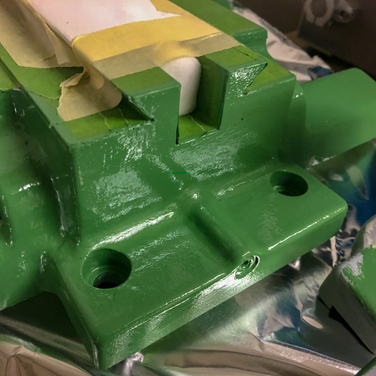
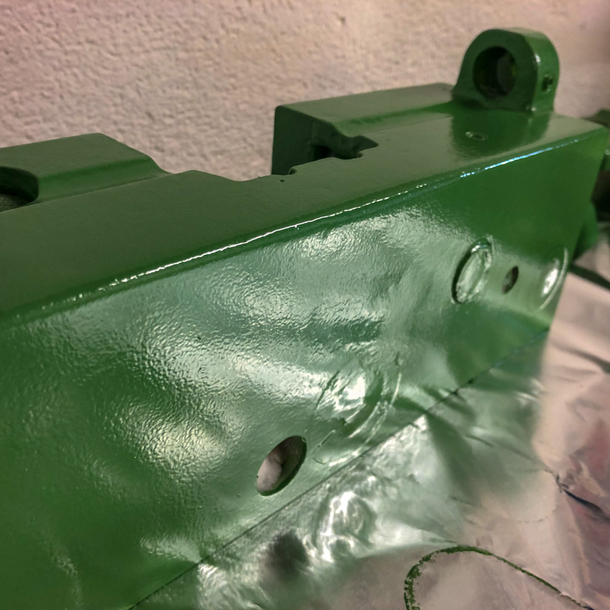
Priming, filling, sanding and painting
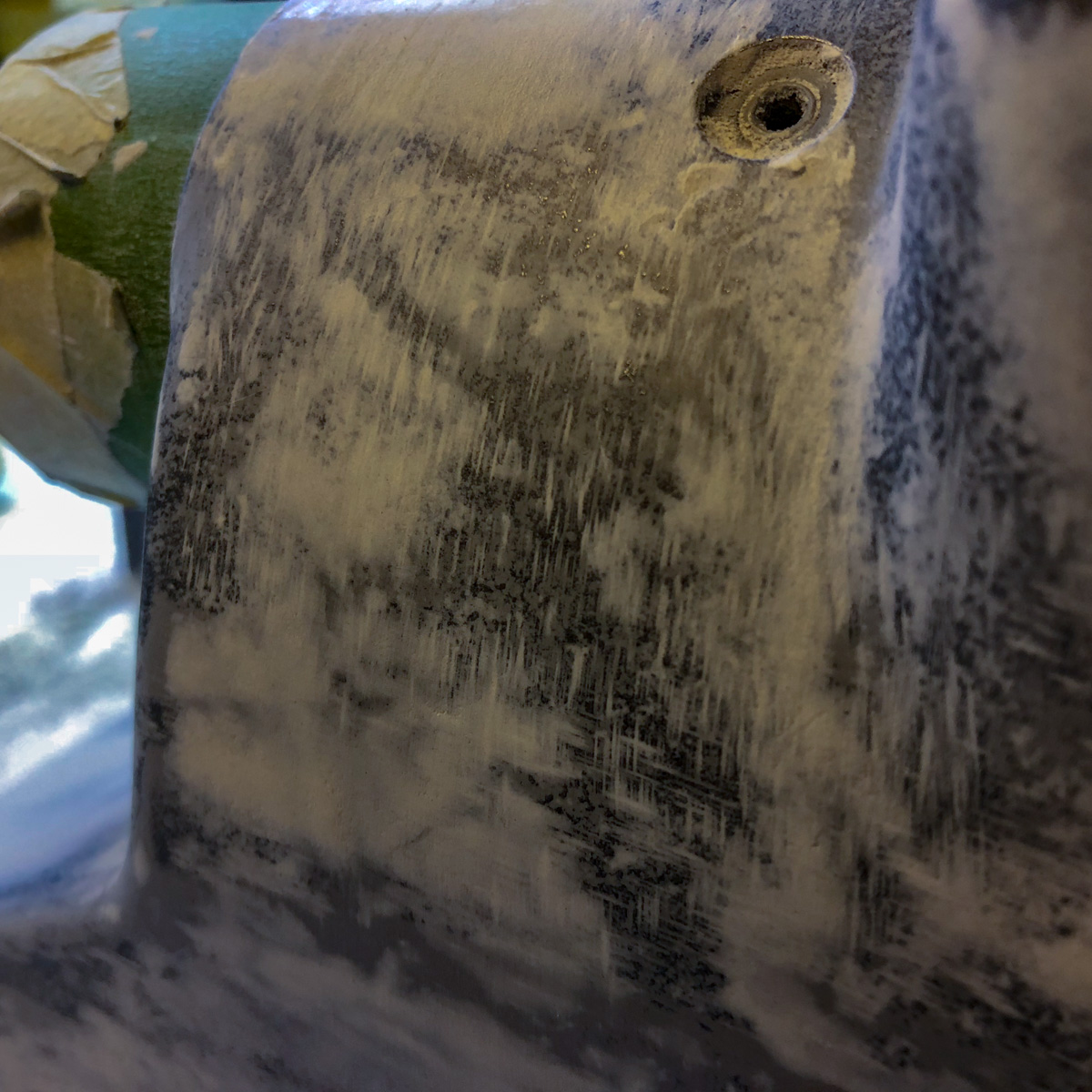
The first steps are tedious, but you’ll be honoured with the results. All coatings are 2K-compounds (primer, putty and the paint). It takes some coats to have a nice, even surface and yes, it’s a mess 😉
The used putty is a two-component-filler with a very short can life. This forces a fast application but has the positive effect, that you can sand the item after a short waiting time.
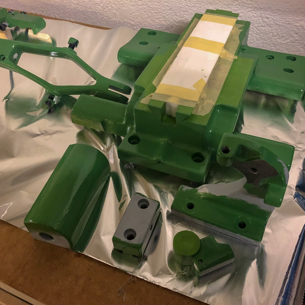
Reassembling
What I’d love to know before
I don’t own the original manual of the machine. There are more than a dozen of manuals on the net: varying languages, different years and diverging types – but all of them in a poor quality. Very difficult to see if a handle is set as a screw or only plugged or plugged and pinned. After studying the manual and inspecting the part from all sides (more than once), you could use a pair of pliers or even the soft-head hammer.
Yes – they were doing a really gread job, manufacturing this machine. I never saw such thight seats! And if the machine’s old and «crusty», it takes some gentle force to convince a part to move…
Don’t remember where I have found this one, but I liked the idea:
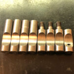
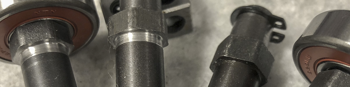
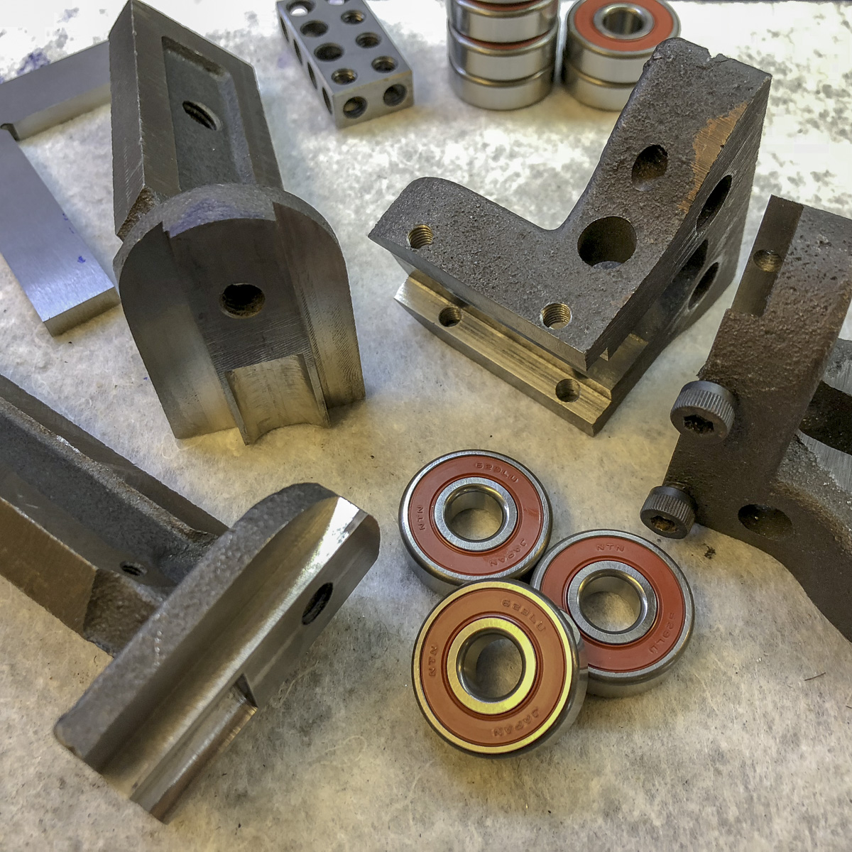
The two on the left: the reduced drive shafts
The offset bearings
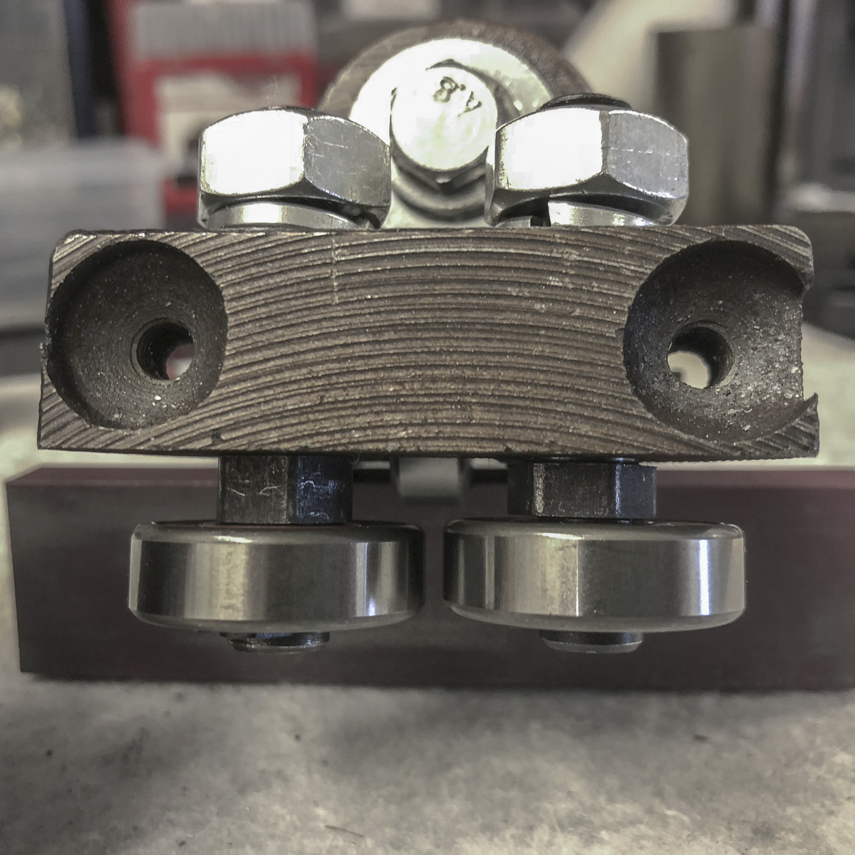
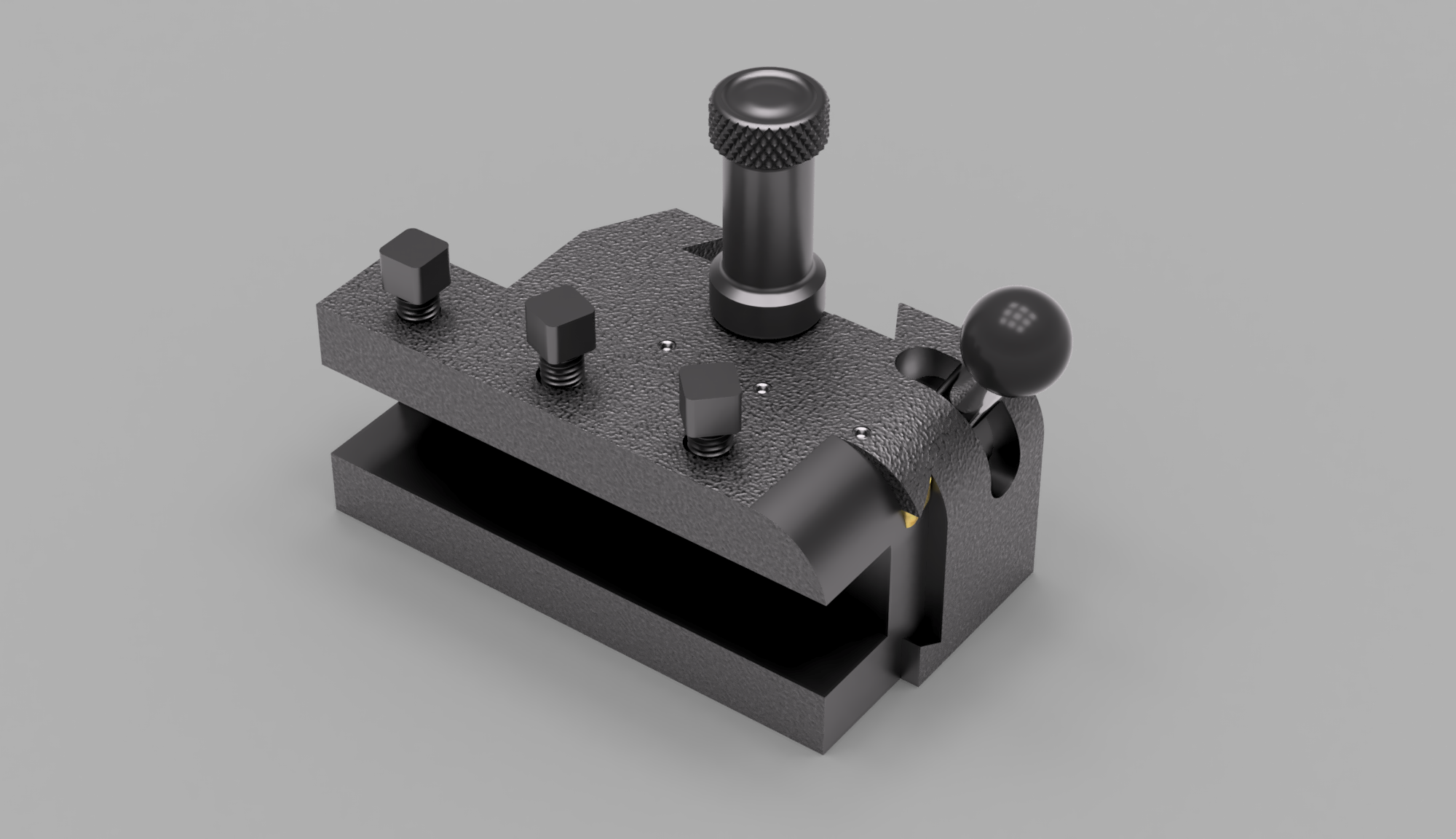
The whole assembly
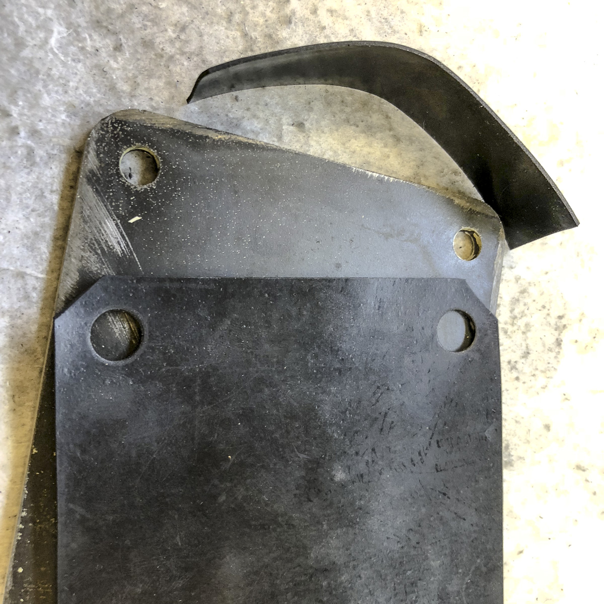
The blade needs to be «bent» in place mainly on two points (on the top right, and the opposite left). The concept of displacing the bearings in accordant way could preserve them a little bit. And given that this is a short task on the lathe…
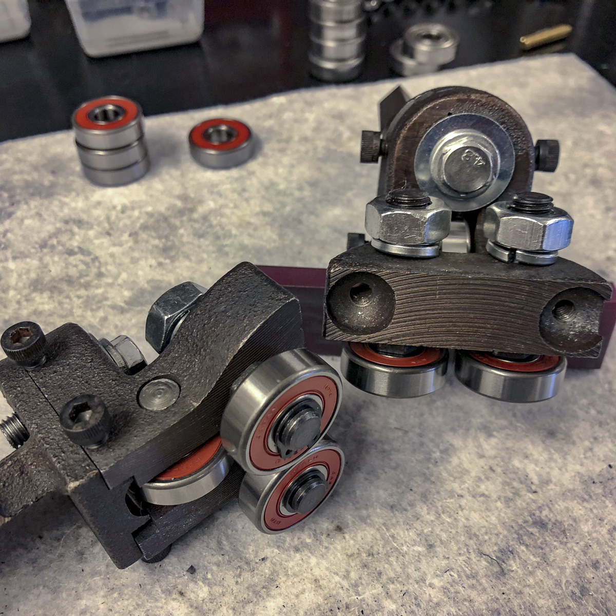
The idea of easing up the setup of the blade alignment is really delightful. I saw this or similar mods on different places – the one I took a in depth look onto was on the ToolsandMods website.
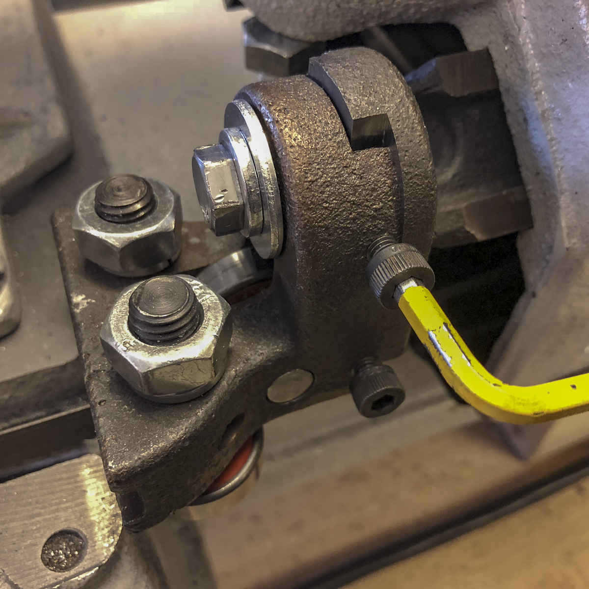
Mine consist of two setscrews on each side of the blade guides – this way it’s possible not only to tilt the blade, but also to displace sideways the whole block. This way it’s really easy and accurate to set the blade in two angles: in the cutting direction and also in the cutting angle of the piece beeing cut.
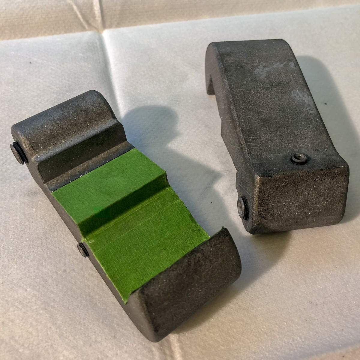
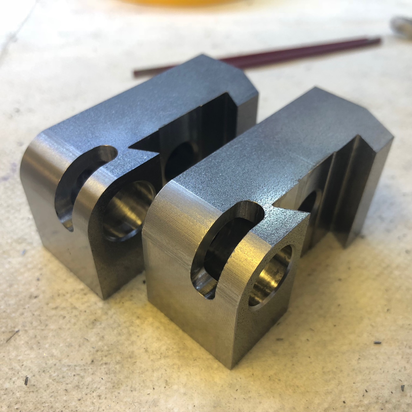
The component parts: milled and tapped guide elements and some new bearings
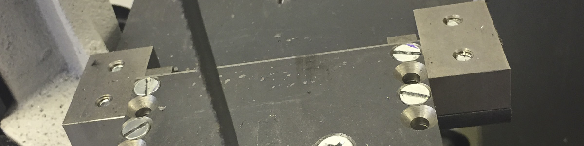
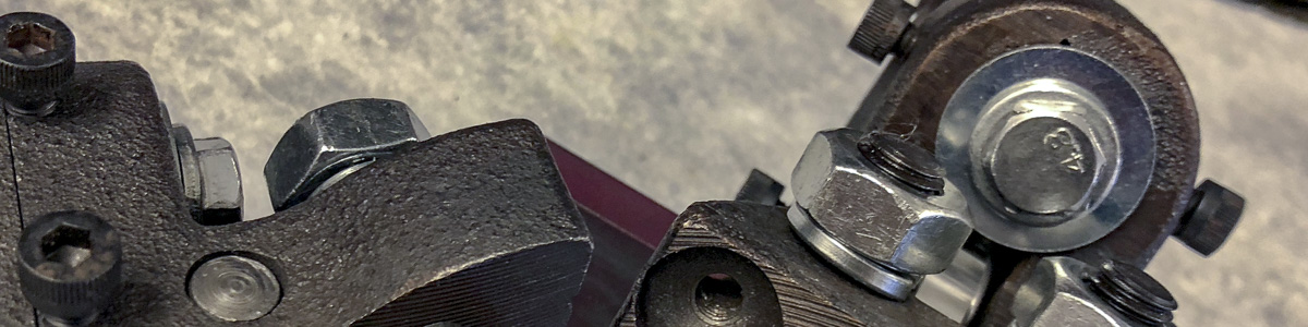
The milled down parts with the two setscrews of this side
The parts were milled about 5.5 mm down on the sides – making space for some M5-threads and offering contact points for the setscrews. Setting this part back, some clearance for the height limiting wheel is needed. I took about 3 mm – you can see this recess in the middle of the part.
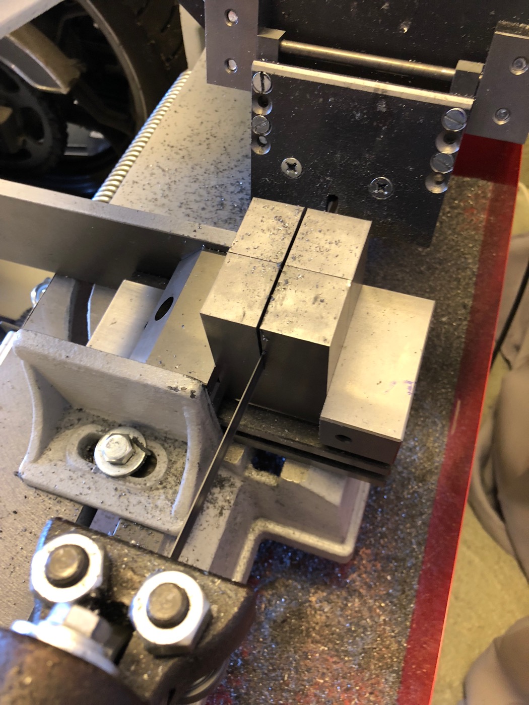
I used some vee blocks to clamp the angled parts down. Don’t worry: those angles are far away from 45°, but this doesn’t matter to the later purpose. The other parts were clamped on the precision tool vice using a ball and some brass shim stock (similar setup as you probably would use to square up stock).
Beneath the usual mess with cast iron, it turned out well. This mod is really a great simplification of the setup process. It speeds it up and makes it really more precise. I really recommend this one!
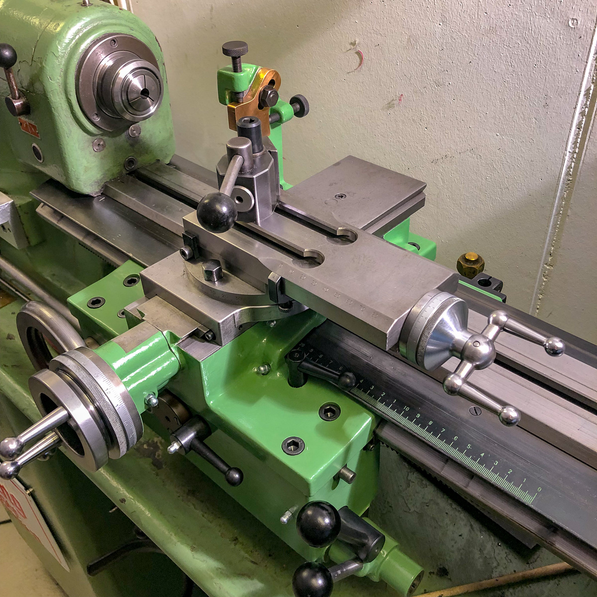
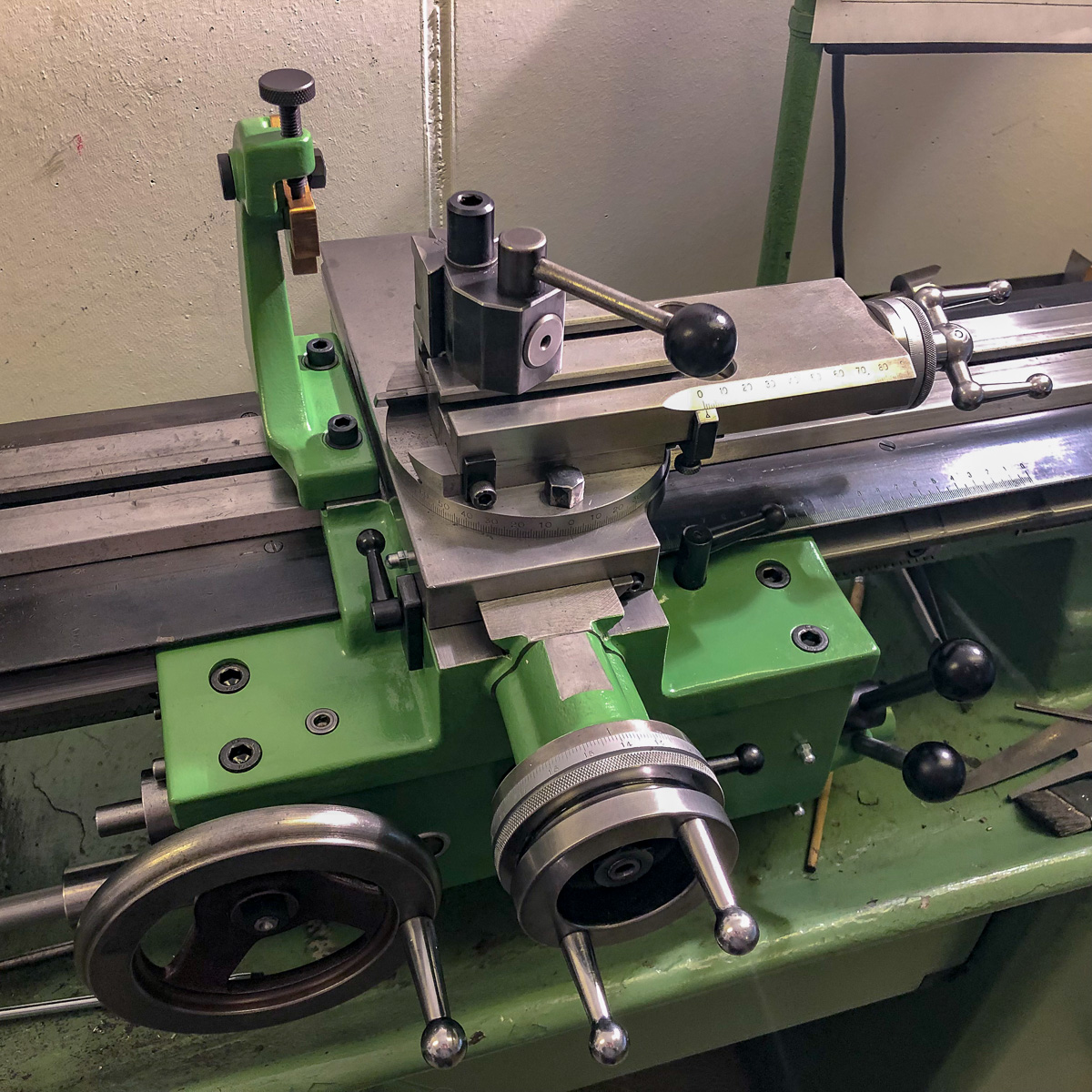
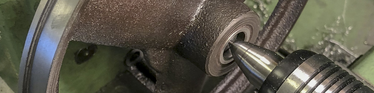
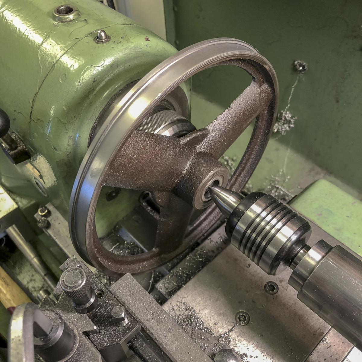
First step: checking out, if the wheel fits the lathe 😛 This bandsaw did a great job for about two years now, and if the wheels couldn’t be trued up on the lathe, I would have kept the things as they were. As you see on the image, it worked!
The wheel fits the Schaublin 102VM really close
Decent finish taking only light cut to true things up
Measuring the upper and lower wheels resulted in a light offset of the whole surface. Not that much, but as the wheel was on the lathe, this was a short thing to fix.
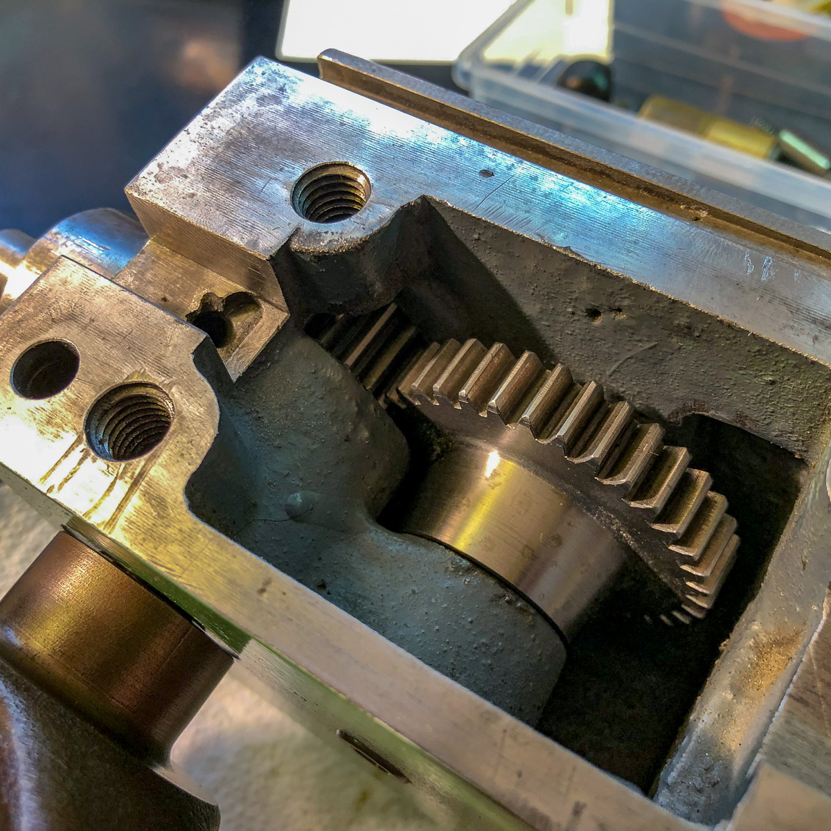
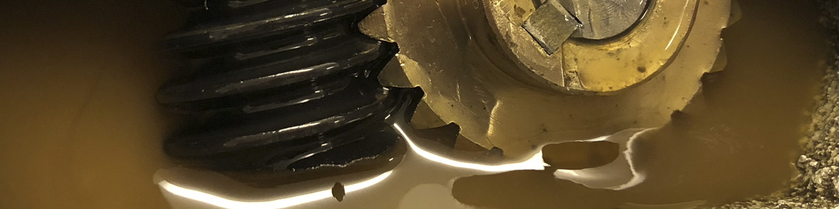
Inside the gearbox, everything looked nice: no worn gears, just a tiny amount of play. I did open this already as I received the machine. Yep, with the whole mess of oil pouring out – so if you didn’t open it yet, be prepared and have some rags on hand.
New gasket made some rubber seal
Filling up to this height is enough to keep the gears lubed
Probably this was the cause of screwing this lid that much down, that I completely thinned the gasket. Well then: a new gasket with some scrap 1 mm rubber plate is done fast – and don’t forget not to overthighten the lid. I need to confess not beeing aware of the different oils and lubrication possibilities – I believe what’s indicated on the label. So far, it worked for me…
As I got some scrap rubber of cutting the gasket, I laid some underneath the junctions of the sheet metal box containing the belt and the pulley gears and the top of the cast iron arm. This really reduced the noise of this resonance box!
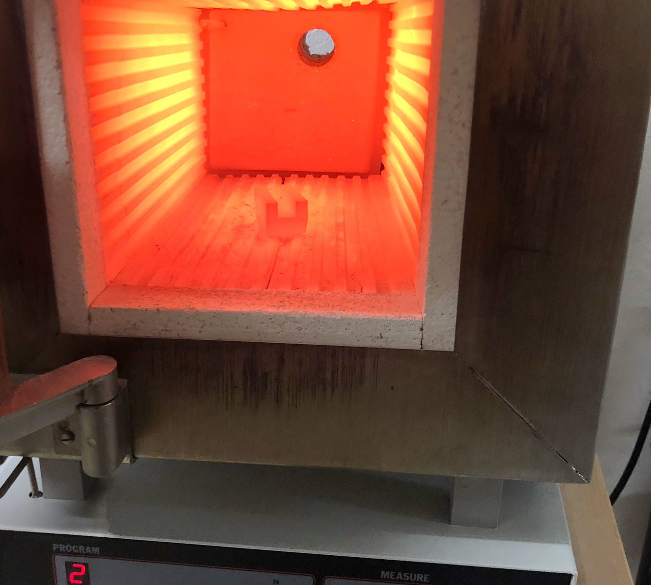
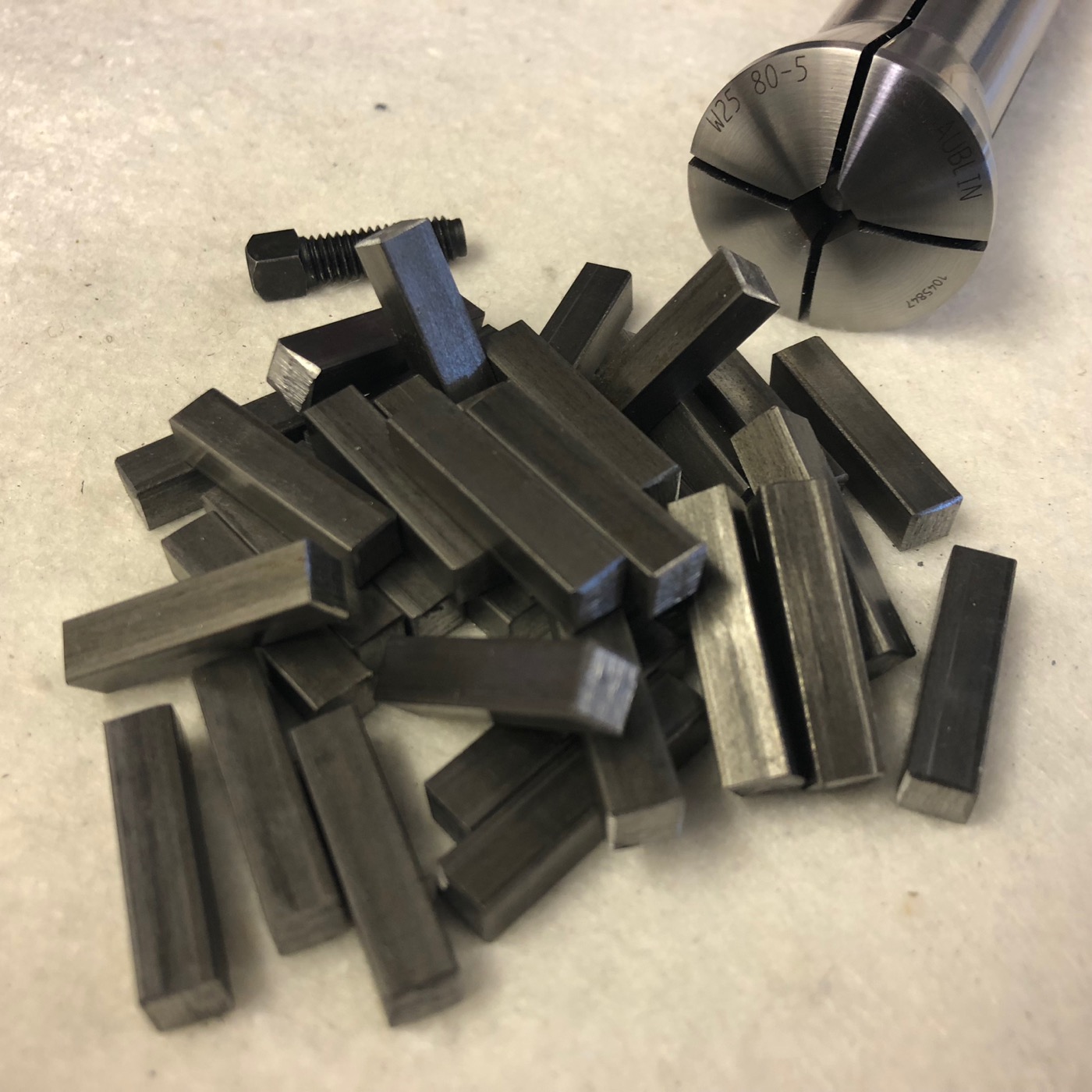
This low carbon steel is not the best material to test the hardening capabilities of the furnace. Therefore I tried to make some heat treatment tests.
The first part (in the oven on the featured image) was an Tripan toolholder which was messed up. This item was heated up to something about 900°C and quenched in tap water. The result is not that uniform as on the second test.
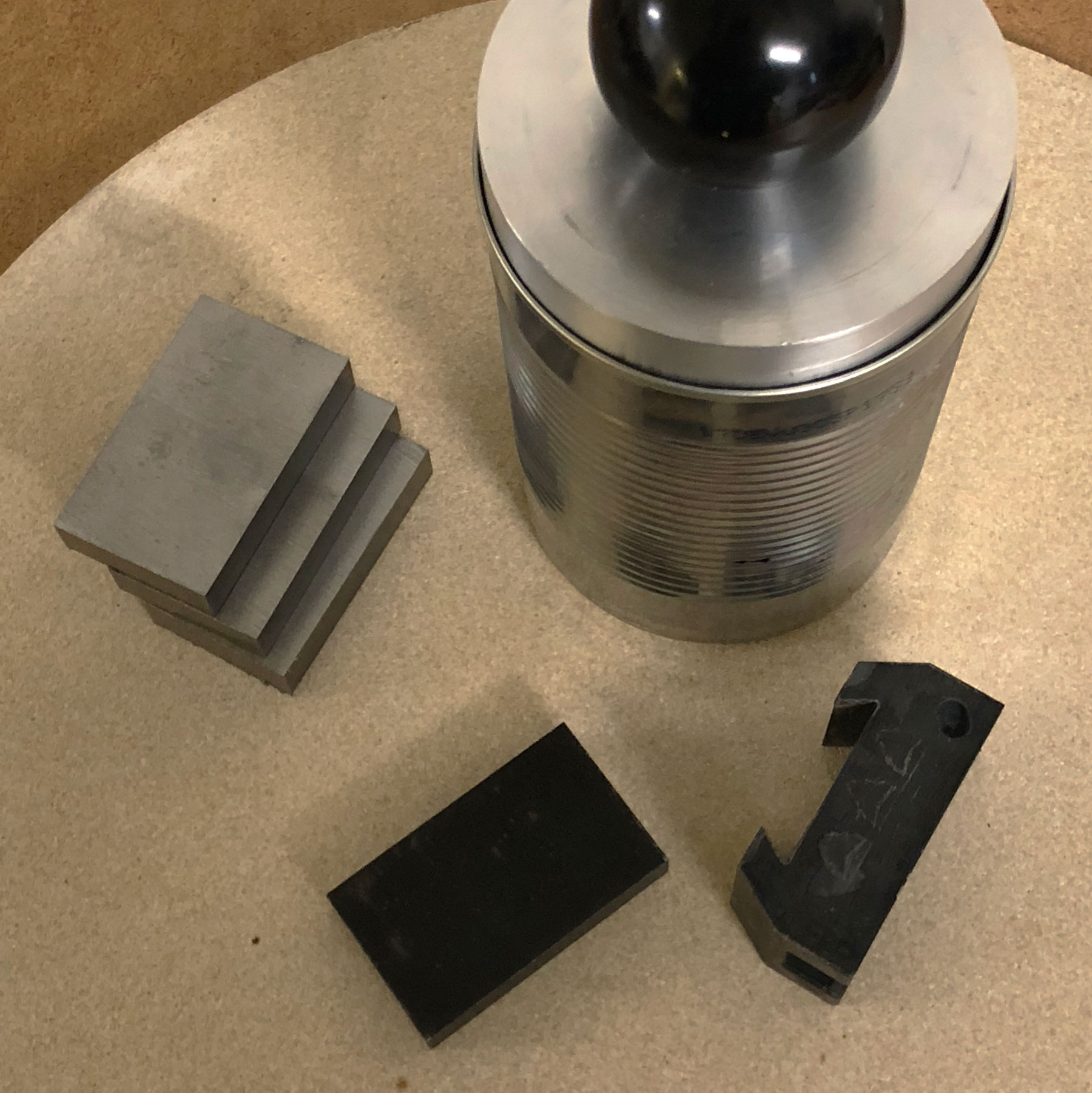
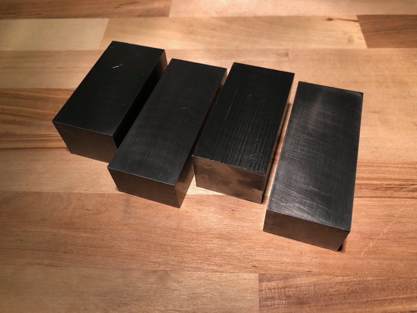
The second part is the first of a row (the raw pieces can be seen on the left). This one was heated to about 600° C and quenched in oil. It went to a nice dark colour…
I really liked the idea of Jim Schmitt (on a post here) about the «inverted» retractable threading tool. Based on the concept of Charles Dolan (his post is here) it reverses the pull-handle to a push-handle – what in my opinion eases different things.
On the one hand, it’s easy to add a spring, helping to fully retract the tool completely in the right moment. On the other hand, it’s possible to let the tool clip into place by the right angle of the mechanism (and supported by the spring). This way it should be possible to cut repeatable and precise threads on the lathe.
Mechanism
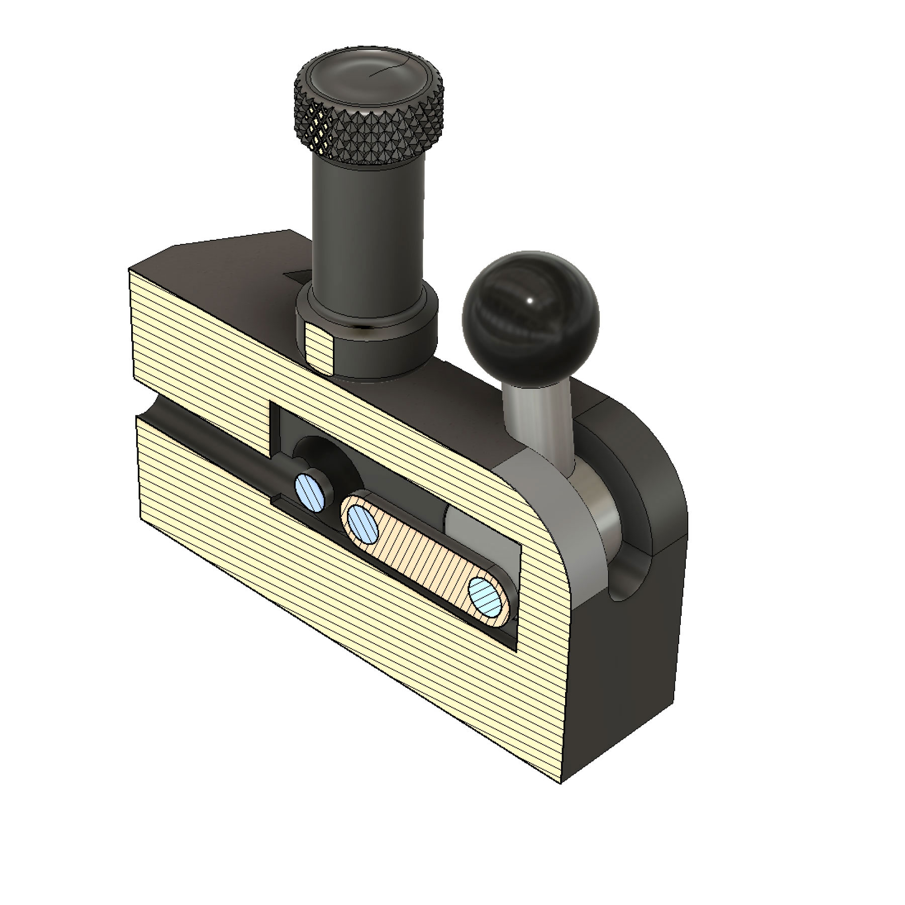
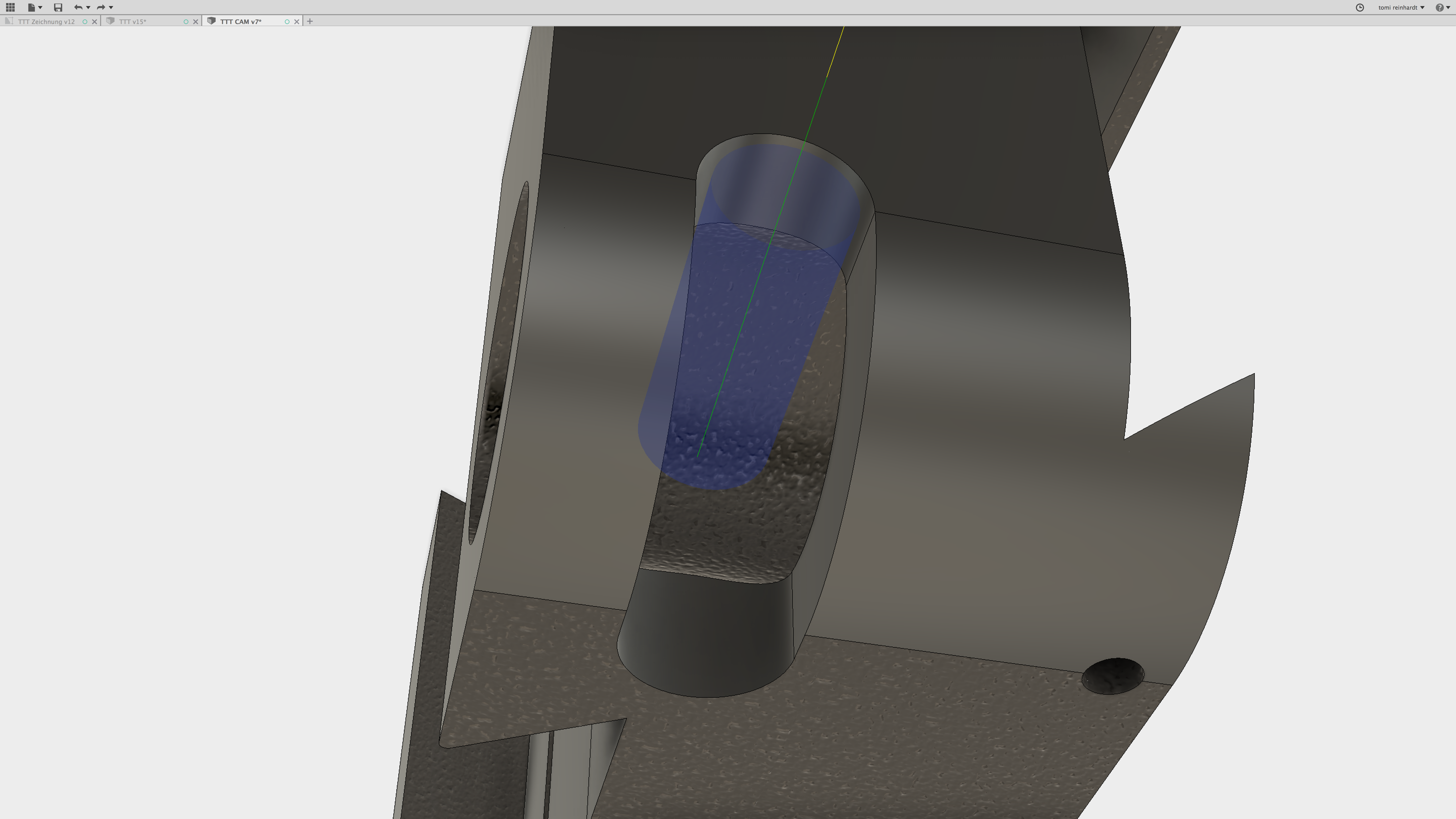
The first sectional view shows the lever mechanism in neutral position.
The through hole on the left is tapped on the end and holds the spring. The two blue circles next to each other are the pins on the slider – the last one from on the lever.
In neutral position, the spring-rod pushes the carriage and the lever back. The lever is in the upper position.
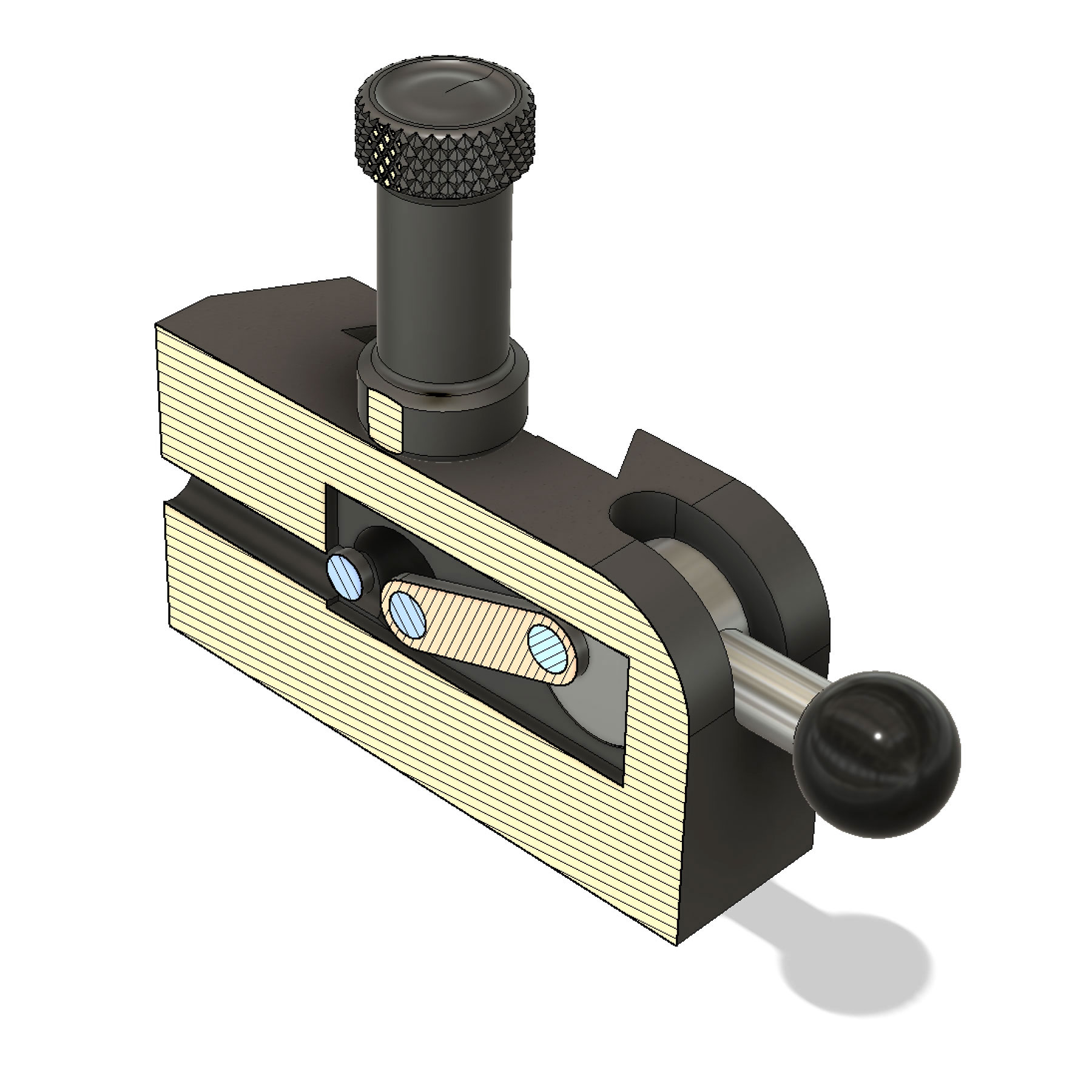
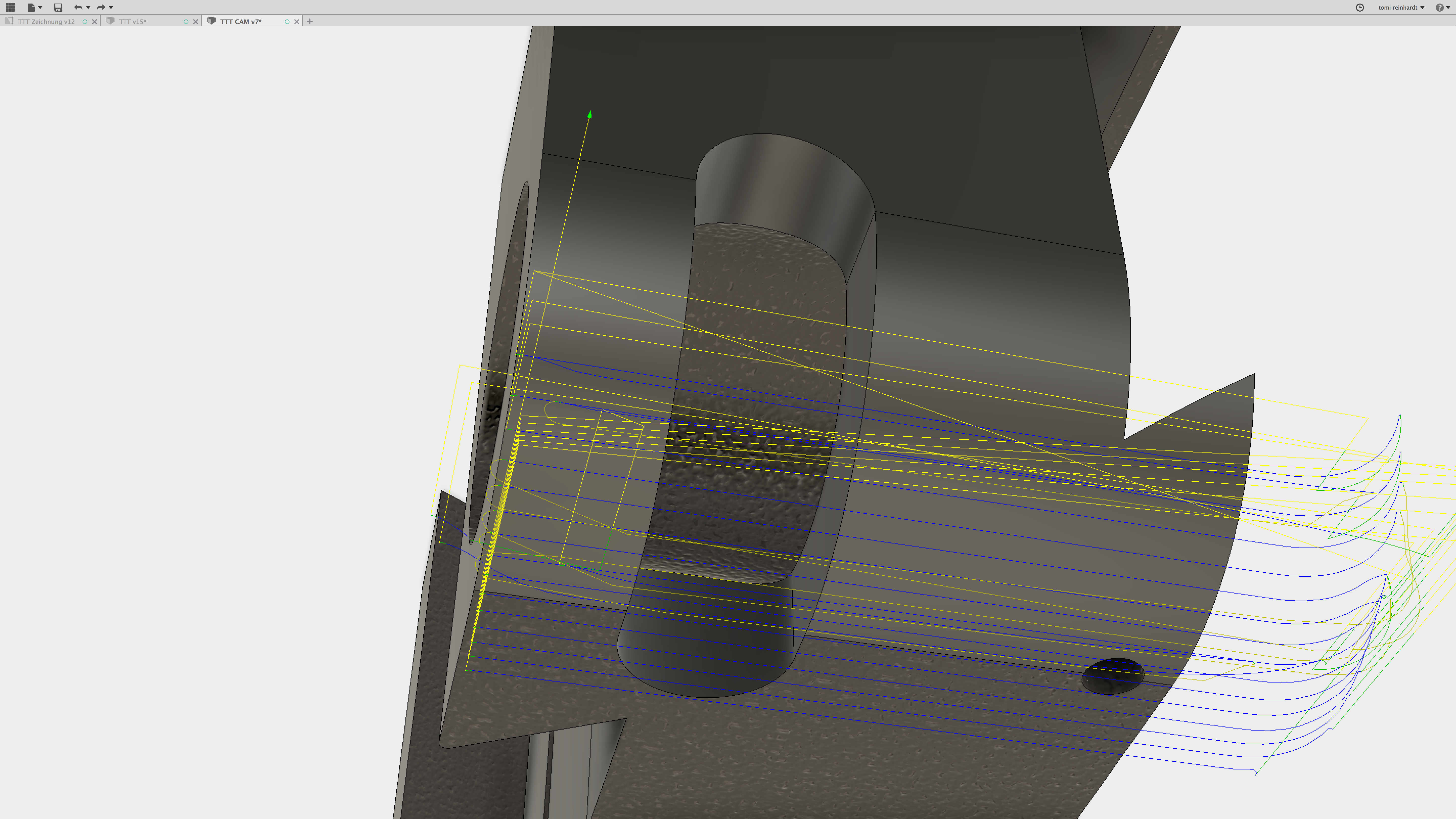
In the activated position, the angle of the link in relation of the lever circle is slight above the center. In combination with the spring tension, this latches the setup in an safe engaged position.
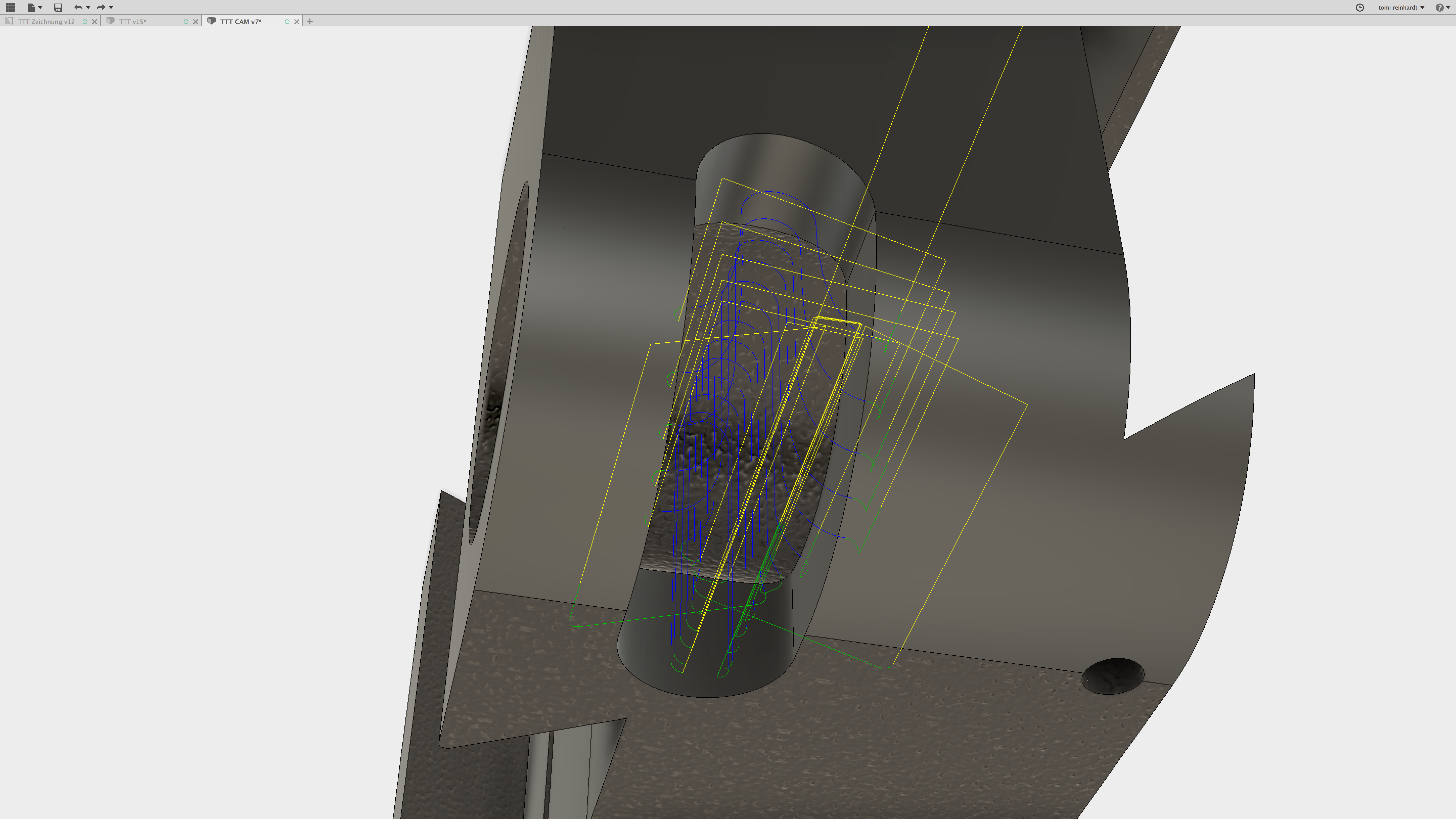
Desengaging the tool needs minimal action and force – as soon as the angle drops below the center of the lever, it’s retracted by the force of the pushing spring rod.
Making
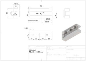
The tool is made of 1.0570 (S355J2+C, or in the USA: 1024). This is low-carbon steel and not really made for hardening (possible tough) – don’t know yet, if this tool needs to be hardened…
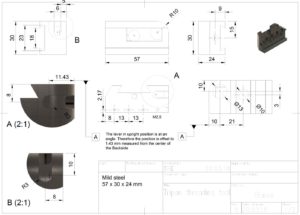
Most parts were milled on the Tormach PCNC440. There were tricky ones, like the dovetails, which need to be smaller than the ones of the back of the toolholder (btw.: yes, also the little version of the dovetail cutter showed on insta works like a charm), or the small cross-section for the lever, which needed a precise angle on the top as back stop. Some screenshots from the «lever side»:
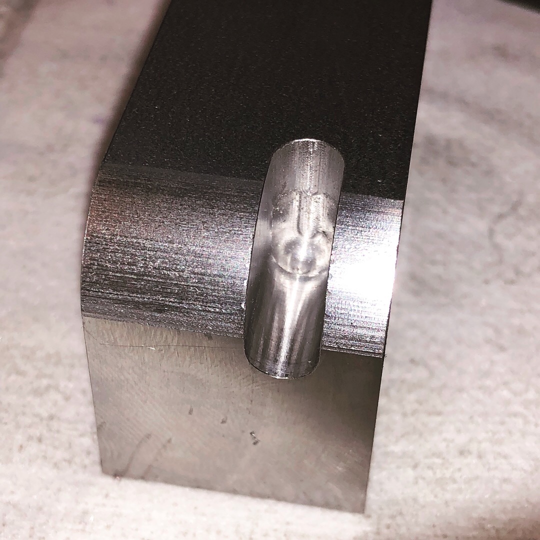
Another difficult part was the axe which connects the slider to the lever: even though it’s possible to simulate almost everything in CAD/CAM, I had to make another version – 0.3 mm longer. It worked perfectly, but in the neutral position, the slider poked out a little bit 😉
After assembly, it turned out, that two pins on the slider was overkill. One is enough – with the benefit, that a stronger ball-point-pen-spring could be used.
Plans
For those who are interested in: here are some PDF-Files of the different parts which were made:
And some photos of the working in progress:
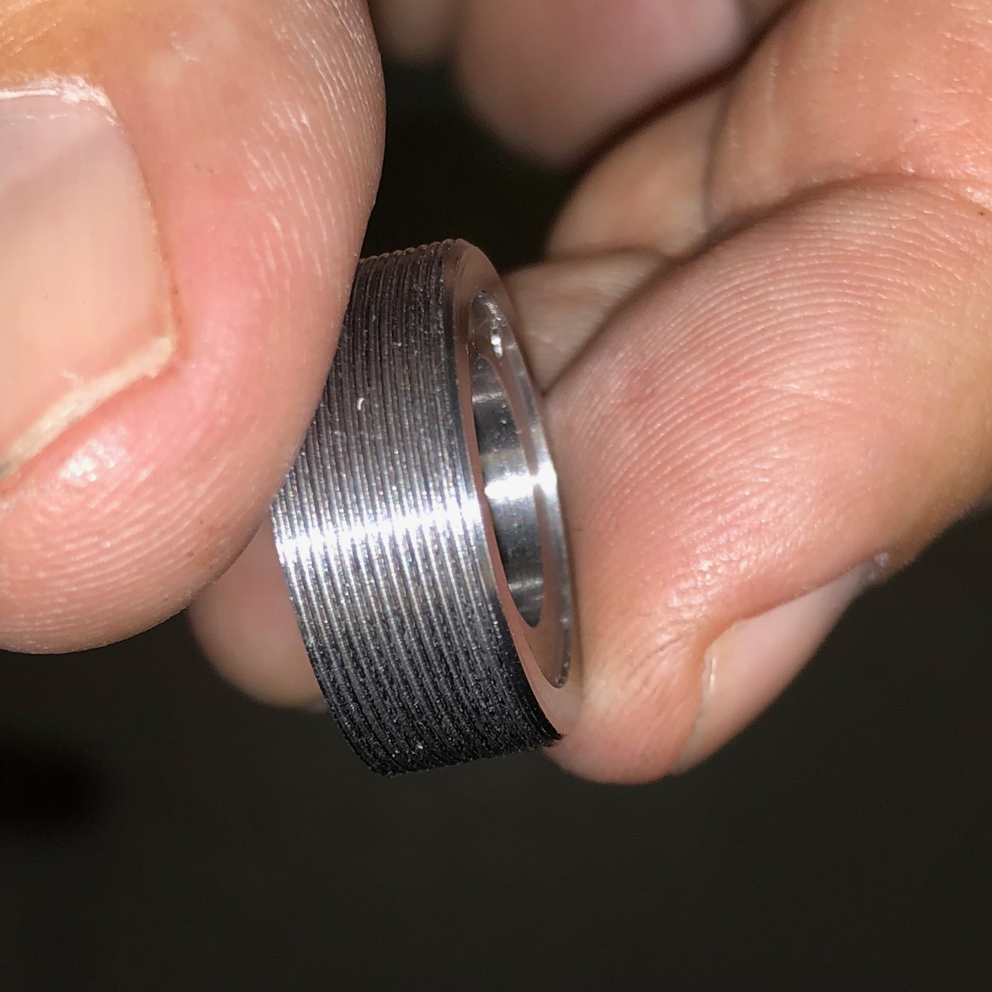
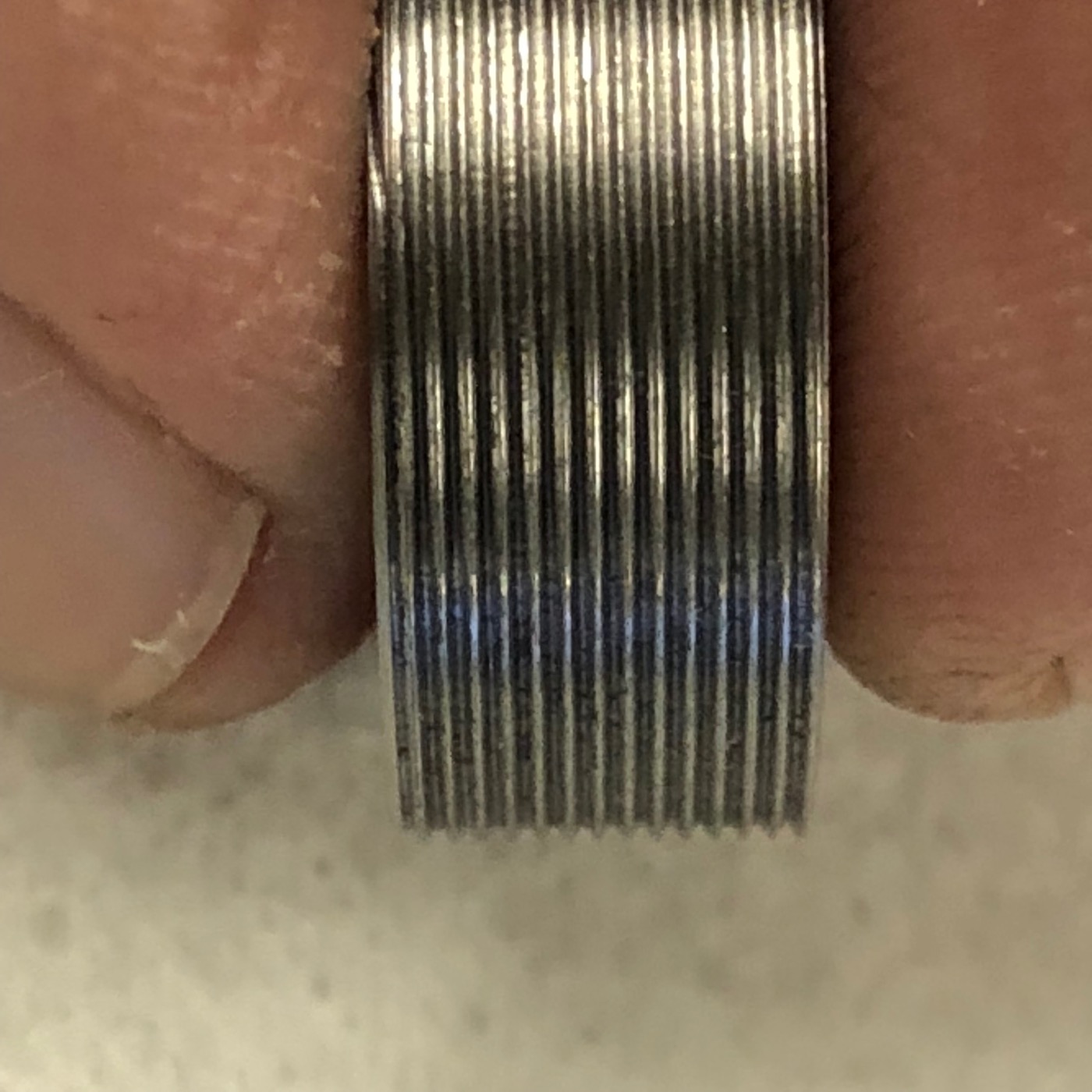
Using the tool
First: the tool works! It’s quite sturdy and won’t move while turning the thread. Though, you really have to set up «soulful» the force of the dovetail clamp. A too high clamping may block the carriage – a too low results in sloppy toolholding!
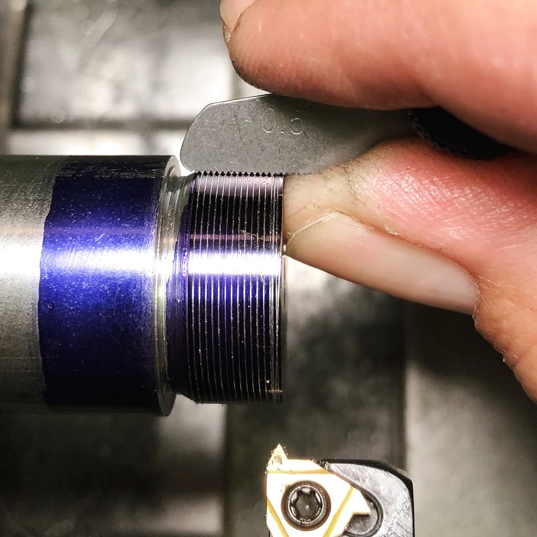
These images were taken from my next project. An M20-something with a fine thread. That was an easy task to do with this tool.