Tripan Toolholder

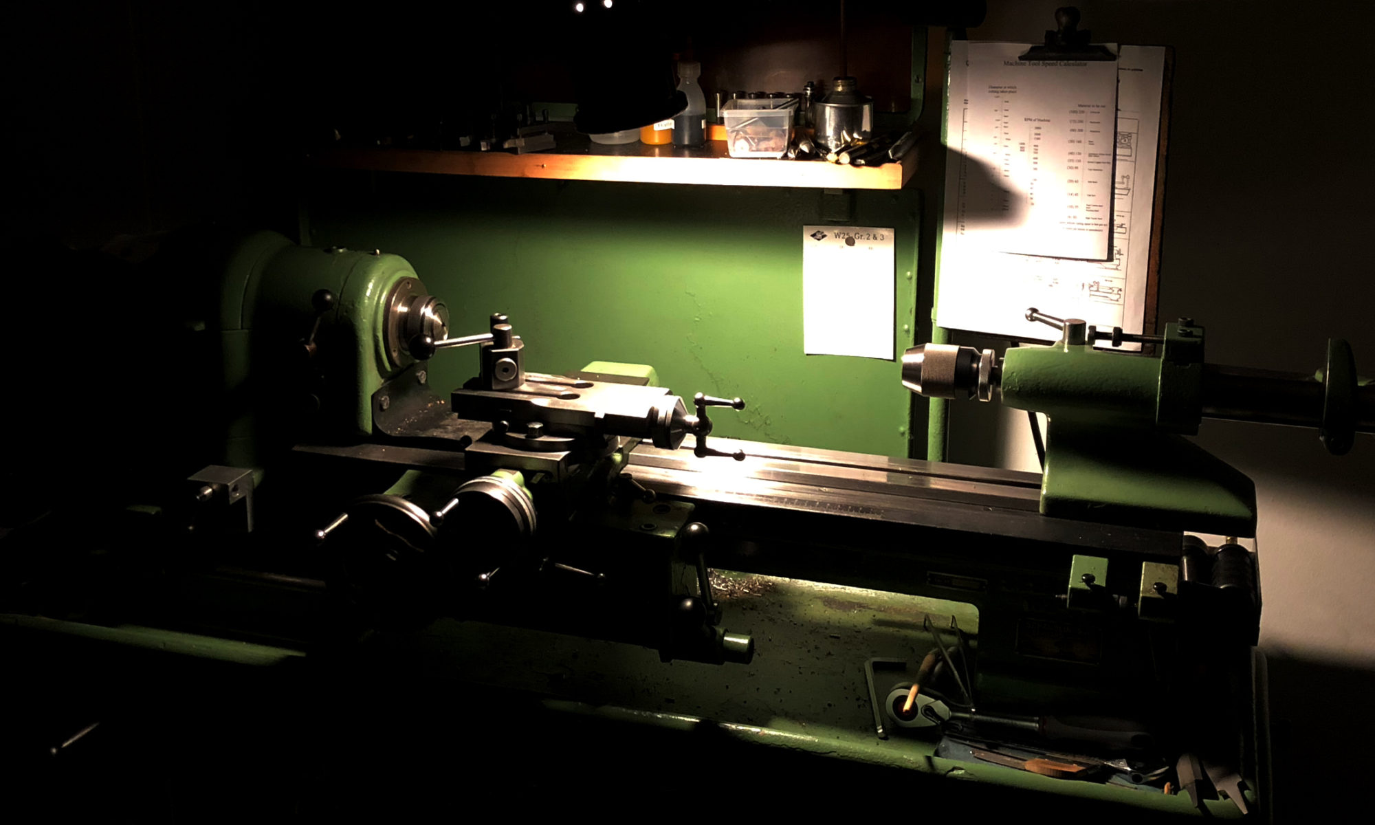
I have a Tripan toolholder system on the Schaublin-102VM lathe. It’s an «old school» quick change system with adjustable height and quite a good clamping capability. I really like the quality and the versatility this system offers – and it matches perfectly on this lathe.

Just because I live nearby where it was produced and probably mainly used, this doesn’t mean, that we could get them cheap – they are still quite expensive (we get them unused for about 85€ p.p.). Therefore and because I’d like to have a better feeling for machining mild steel, I wanted to make a  run of 10-12 of them. Right: about a dozen – a mechanical artist on Instagram about that fact (Thanks Robin):

robinrenzetti Looking good, no such thing as too many tool holders. 💪👍👌

CAM

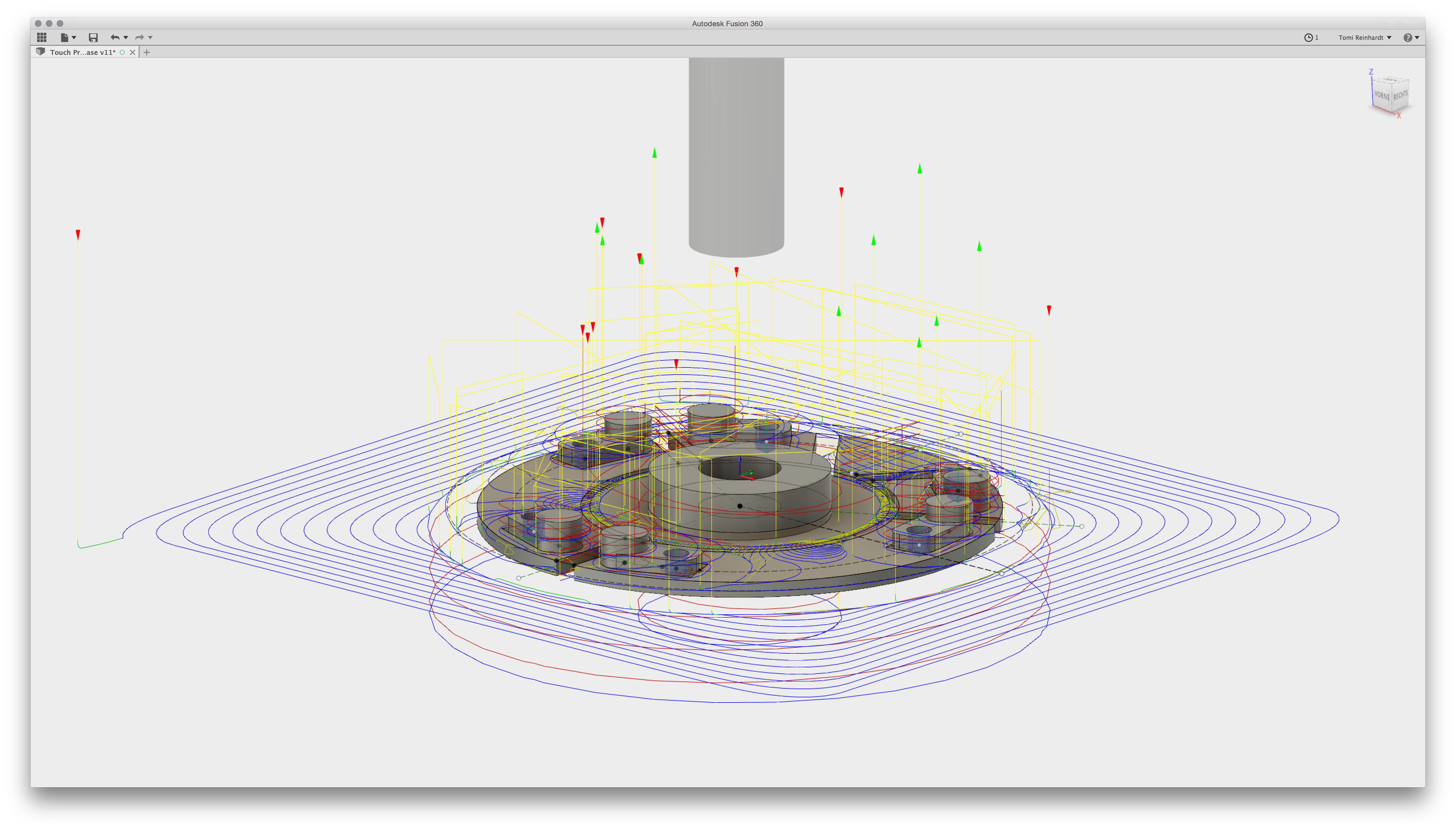
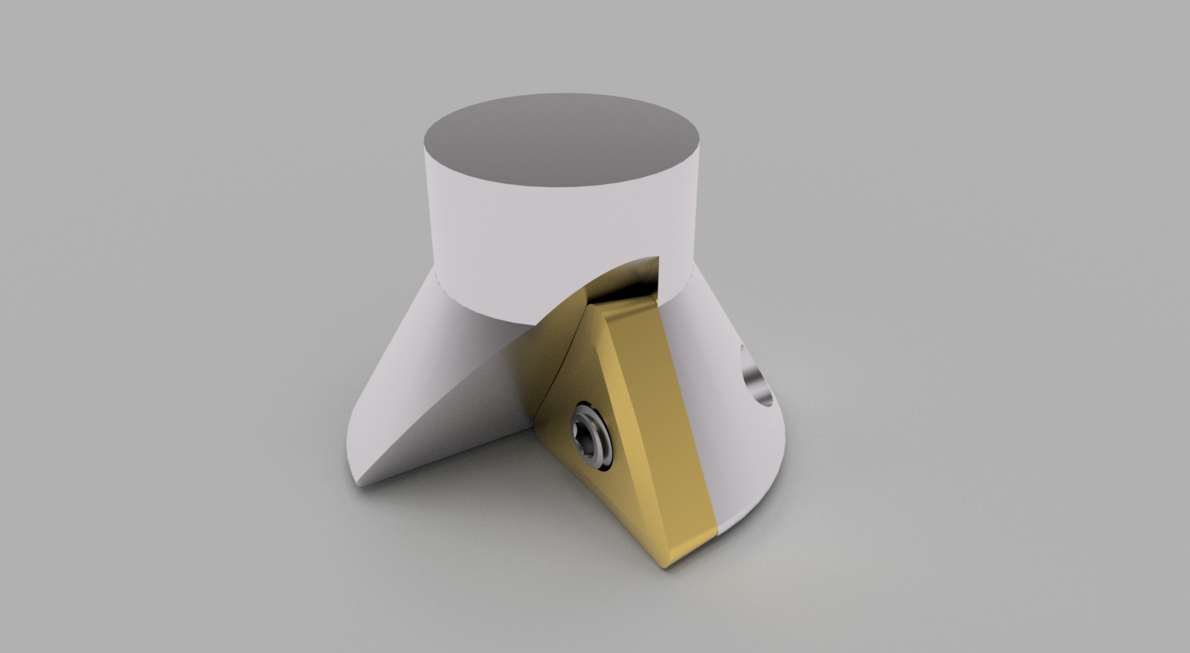
I own some original toolholders – and there are some plans with measurings on the net. So, making a CAD-file out of that material was an easy task. At the moment, my favourite CAD/CAM/Rendering program is Fusion360. Take a look – you can manipulate the image yourself:
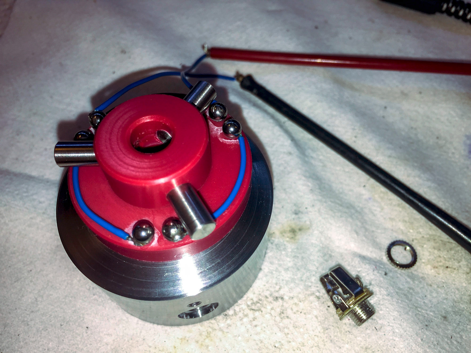
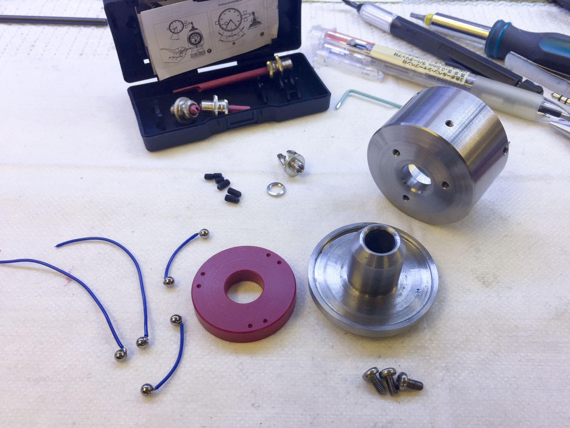
Prototyping

I always like to test some setups, materials, speeds’n’feeds, etc. – even too in the production run! The prototype means the previous step for me: a first physical output, which you can move in your hands and study directly on it. Even though CAM and CAD are quite sophisticated these days, they won’t beat the physical output.

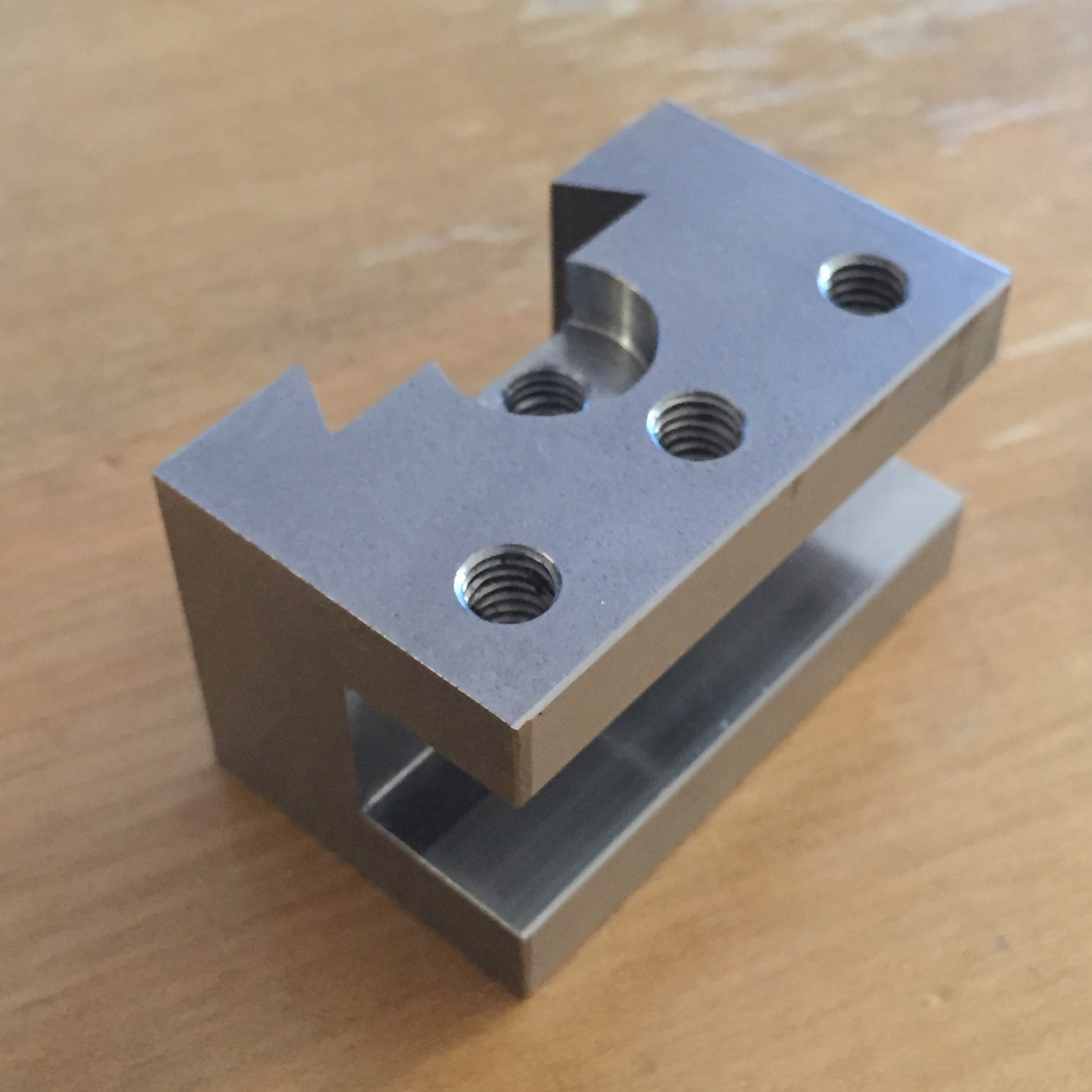
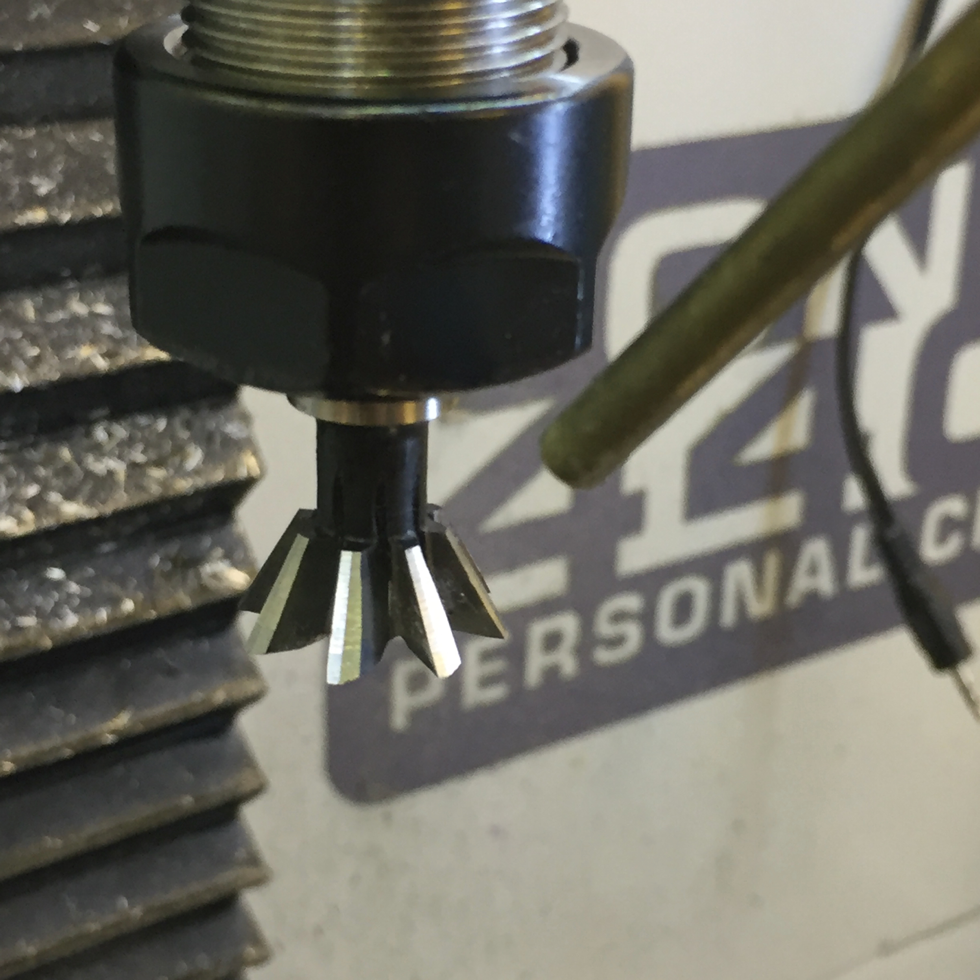
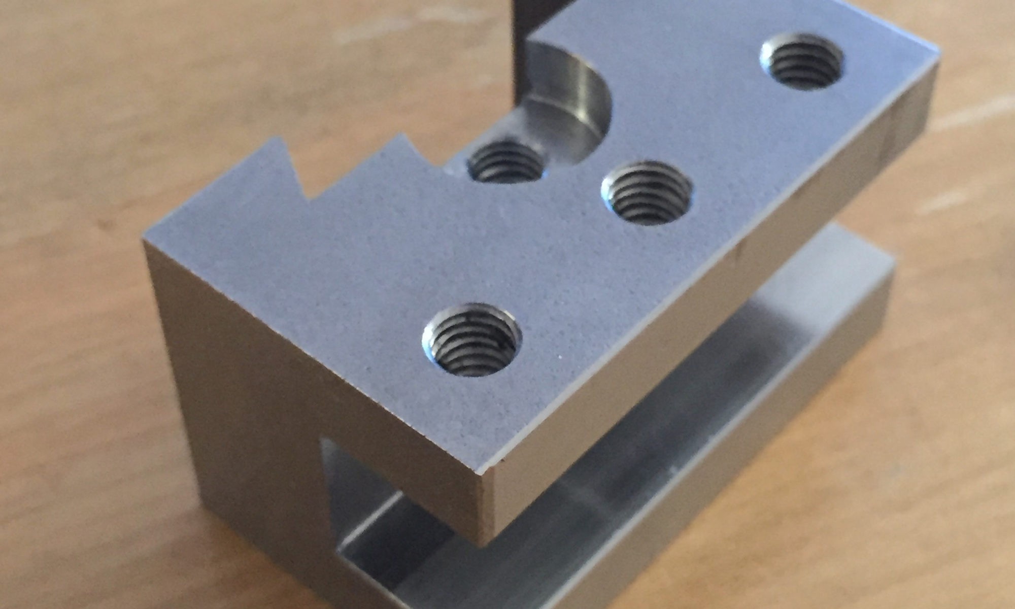
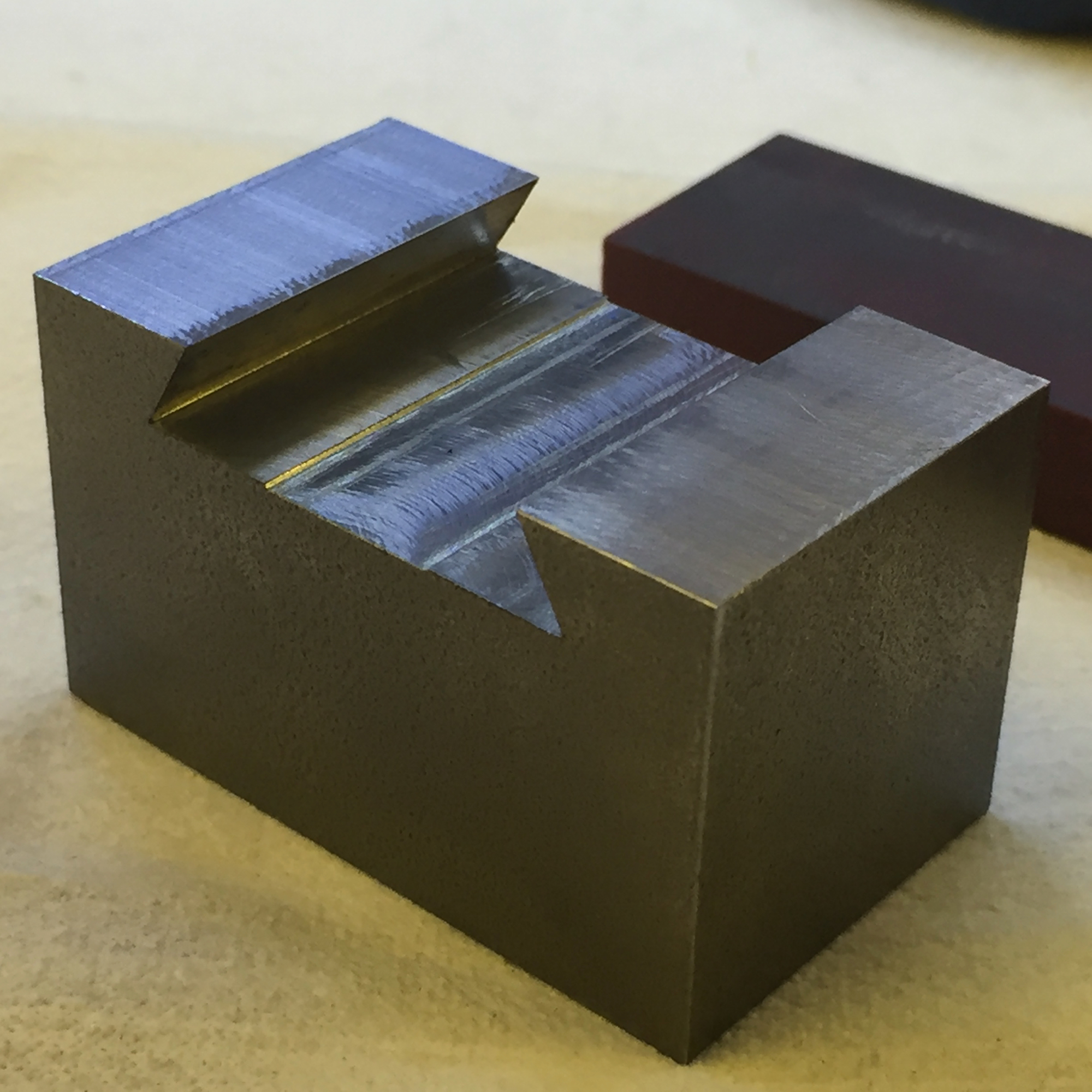
The first prototype turned out well. The dovetail cutter won’t take a whole production run, and there were some «design issues» – but technically the «proof of concept» was done…

CAD

For machining this little piece, three different setups were needed. If you make a production run and have the stock-pieces in the same dimensions, you can ease your life by indexing them in on the lower back inset – this way, you don’t need to bother about heights (you set them in the CAD-program). The mentioned setups are:

  1. Back face – with the dovetail, where the toolholder is clamped
  2. Top face – with the three clamping, and the height adjustement screws
  3. Front face – the one where the tool is mounted

Back face

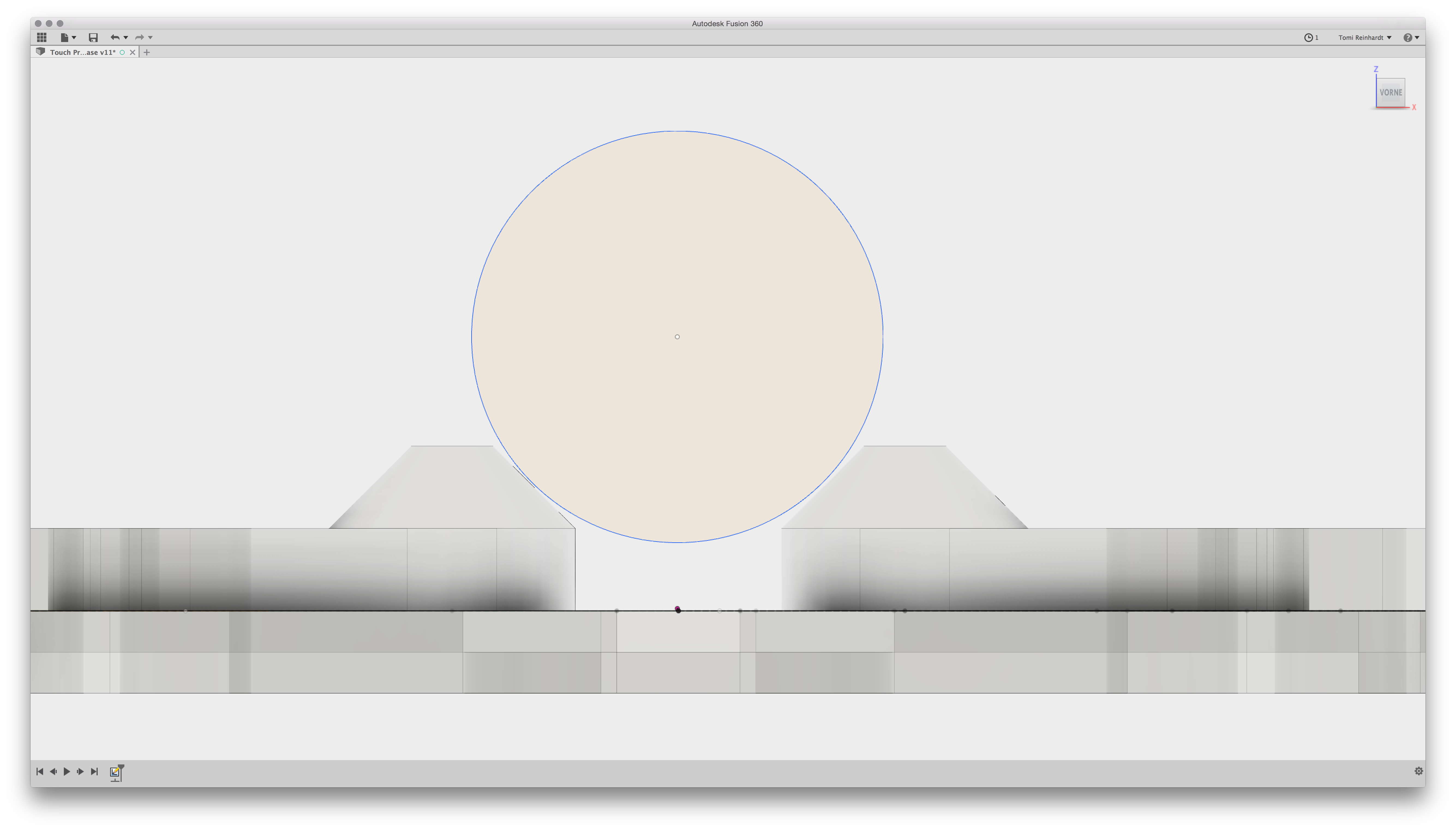
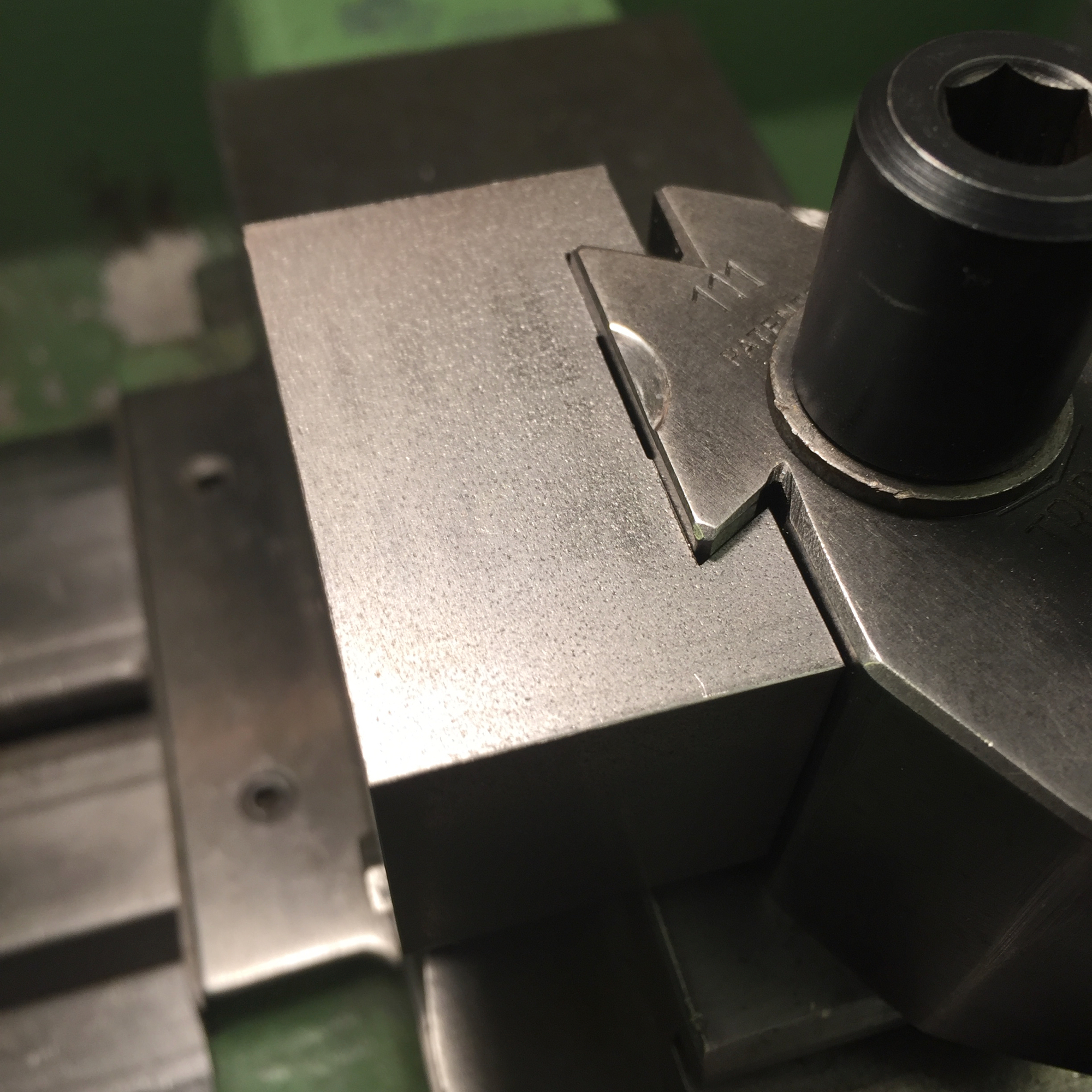
As mentioned above, on the first try I noticed, that tool wear would sooner or later be a issue on the production run. The dyi-dovetail-cutter solved the problem (and lasts till today – after a dozen of dovetails milled).

By the way: the width of the dovetail isn’t that critical in my opinion. On the drawings I mentioned before, really tough tolerances are given. But finally it defines the way the base lever (on the Tripan 111) has to travel – nothing significant for working with it.

The back surface (image above: on the top)

… not finished yet. To be continued…

Merken

Merken

Merken

Passive Touch Probe

For some work, a touch probe appeas to me as the right approach. The most obvious here is the indexing of circular objects like holes or round stock – where one should measure one of the axis twice to get the right middle point.

The tools which are sold are quite expensive. Sure, it’d be precise – but I think with the right concept, it’s possible to make this (otherwise simple) mechanic accurate for my needs. 

The main concept consist of a closed electrical loop with three gaps, which are bridged by rods attached to the probing tip. The CNC notices the input as soon this closed loop is interrupted. Here one of my attempts which illustrates the idea behind:

Six setscrews were integrated in the housing – to calibrate the position and the orientation of the probe tip. Three on the bottom to balance it to the vertical of the CNC-Machine, and three on the side face to bring it in line the the arbor. Take a look to the following image. The top of the case was turned separate with a kind of TTS-collet. It’s mounted to the bottom part – on which you can see four of the six setscrew-threads and the hole on the bottom where the probe-tip-assembly gets through. As probe tip I used some broken ones from the Haimer 3D Sensor – therefore I don’t need a new type and can make some probe tips myself (that’ll be a separate post).

The red plate which is placed inside of the bottom part and the wiring with the 3 mm balls soldered on them is not the final solution. This was the complicated part of the project!

The used material reaches from polyoxymethylen (POM or Delrin) to polyvinile chloride (PVC), brass and copper inlays. Exept the first on the top left, all of them has issues with either the bearing ball (try once to solder them 🙂 or the mounting of the whole assembly (POM and PVC really hardheaded to glue).

The solution I’ve chosen is the milled brass type assembly mounted on «a kind of wooden» base. This version is solid and shouldn’t deform itself – but to be sure: time will tell.

The model and the G-Code for the milling machine was generated in Fusion 360. I milled it directly glued on the «kind of» wooden base – if the glue’s cured correctly, the part shouldn’t break.


This way I got two basic advantages: probably the milling machine is more accurate than glueing some stainless-steel-bearing-balls and it’s really easier to plan such an assembly with gaps being bridget with some rods:

So there we go! The finished assembly mounted in the base and wired on some standard 3.5 mm headphone jack which leads to the CNC-machine:

First test: the probe works fine. Don’t know yet about the accuracy, I need to dial it in and do some calibrations first. But I’m already satisfied, that the concept works and that the probe tip doesn’t get crushed in the first tries…


Additional edit after setup and adjustment

The adjustment is very easy to do in the Pathpilot software.  With a little patience, it’s possible to get close to some hundrets of milimeters, which is enough accuracy for my daily needs. Here you can see the output while adjusting it:

Patience! It lasted until 4/100 mm for me 😉 

The usage is simple, but for my person: not as fast as the Haimer. At least for the standard setup – for dialing in prepared stock or holes or such things, this probe will still be my first choice!

Merken

Merken

Merken

Dovetail cutter

For my Tripan-toolholder-project i needed a 60° dovetail cutter. I got one which worked really great with the prototype:

After inspecting the work and the tool, I saw a beginning wear in the tool. Those tools are to expensive to get them stub after 2 or 3 parts. So, I thought about an indexable tool – but they are even more expensive than the solid ones! Consequence: make an own one. Continue reading “Dovetail cutter”