Tripan tool holder

Simple but convenient – tool organisation for the tripan toolholders! This is what it looks like at the end of the day…

The layout is set «by eye». After some weeks using it, I would change this and give some more space for «overlength» tools. Luckily some pins were used to fix the bent parts! This gets handy if you rework the layout – just change the pins.

Bandsaw – fine adjustment on the blade guides

The idea of easing up the setup of the blade alignment is really delightful. I saw this or similar mods on different places – the one I took a in depth look onto was on the ToolsandMods website.

Mine consist of two setscrews on each side of the blade guides – this way it’s possible not only to tilt the blade, but also to displace sideways the whole block. This way it’s really easy and accurate to set the blade in two angles: in the cutting direction and also in the cutting angle of the piece beeing cut.

The parts were milled about 5.5 mm down on the sides – making space for some M5-threads and offering contact points for the setscrews. Setting this part back, some clearance for the height limiting wheel is needed. I took about 3 mm – you can see this recess in the middle of the part.

I used some vee blocks to clamp the angled parts down. Don’t worry: those angles are far away from 45°, but this doesn’t matter to the later purpose. The other parts were clamped on the precision tool vice using a ball and some brass shim stock (similar setup as you probably would use to square up stock).

Beneath the usual mess with cast iron, it turned out well. This mod is really a great simplification of the setup process. It speeds it up and makes it really more precise. I really recommend this one!

Bandsaw – gear and pulley box

Inside the gearbox, everything looked nice: no worn gears, just a tiny amount of play. I did open this already as I received the machine. Yep, with the whole mess of oil pouring out – so if you didn’t open it yet, be prepared and have some rags on hand.

Probably this was the cause of screwing this lid that much down, that I completely thinned the gasket. Well then: a new gasket with some scrap 1 mm rubber plate is done fast – and don’t forget not to overthighten the lid. I need to confess not beeing aware of the different oils and lubrication possibilities – I believe what’s indicated on the  label. So far, it worked for me…

As I got some scrap rubber of cutting the gasket, I laid some underneath the junctions of the sheet metal box containing the belt and the pulley gears and the top of the cast iron arm. This really reduced the noise of this resonance box!

Tripan style threading tool

Tripan Threading Tool

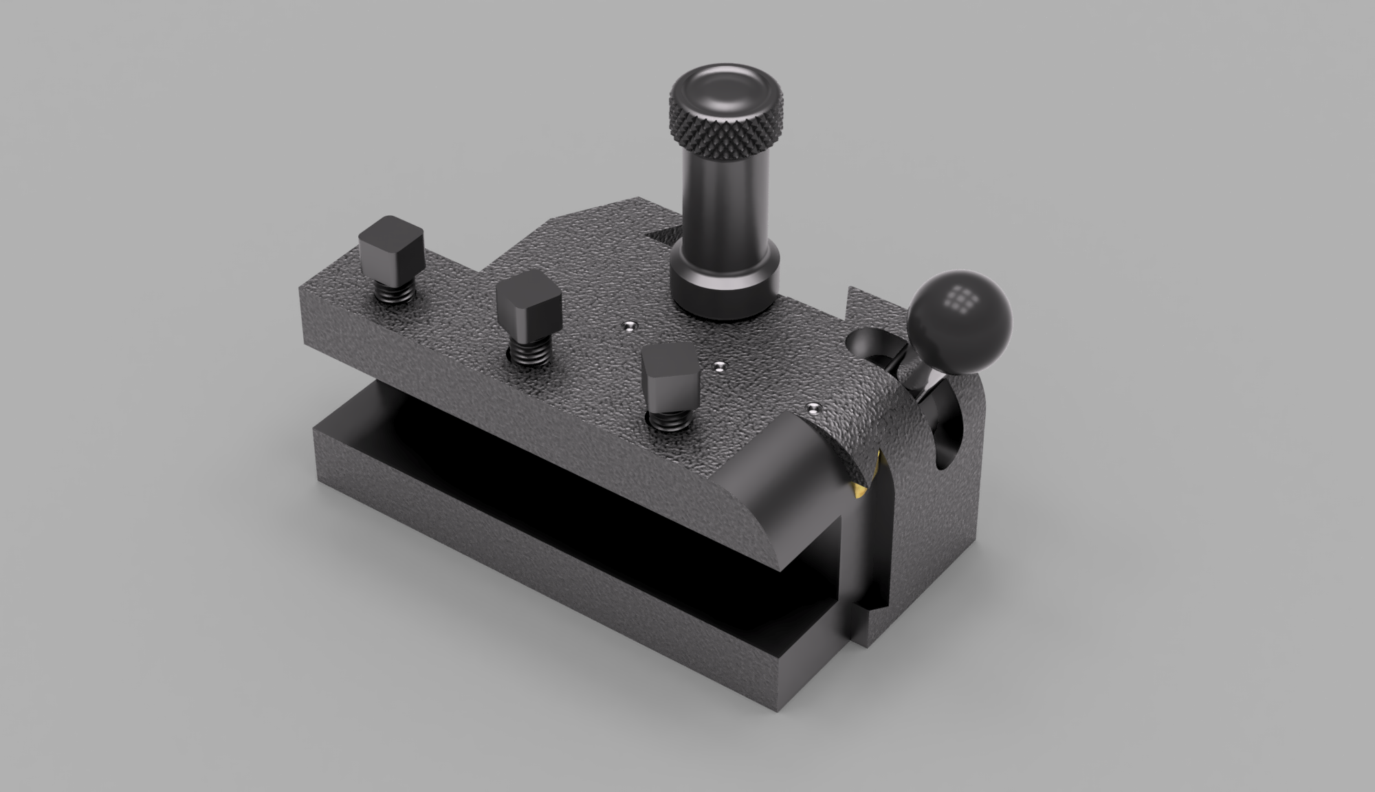
I really liked the idea of Jim Schmitt (on a post here) about the «inverted» retractable threading tool. Based on the concept of Charles Dolan (his post is here) it reverses the pull-handle to a push-handle – what in my opinion eases different things.

On the one hand, it’s easy to add a spring, helping to fully retract the tool completely in the right moment. On the other hand, it’s possible to let the tool clip into place by the right angle of the mechanism (and supported by the spring). This way it should be possible to cut repeatable and precise threads on the lathe.

Mechanism

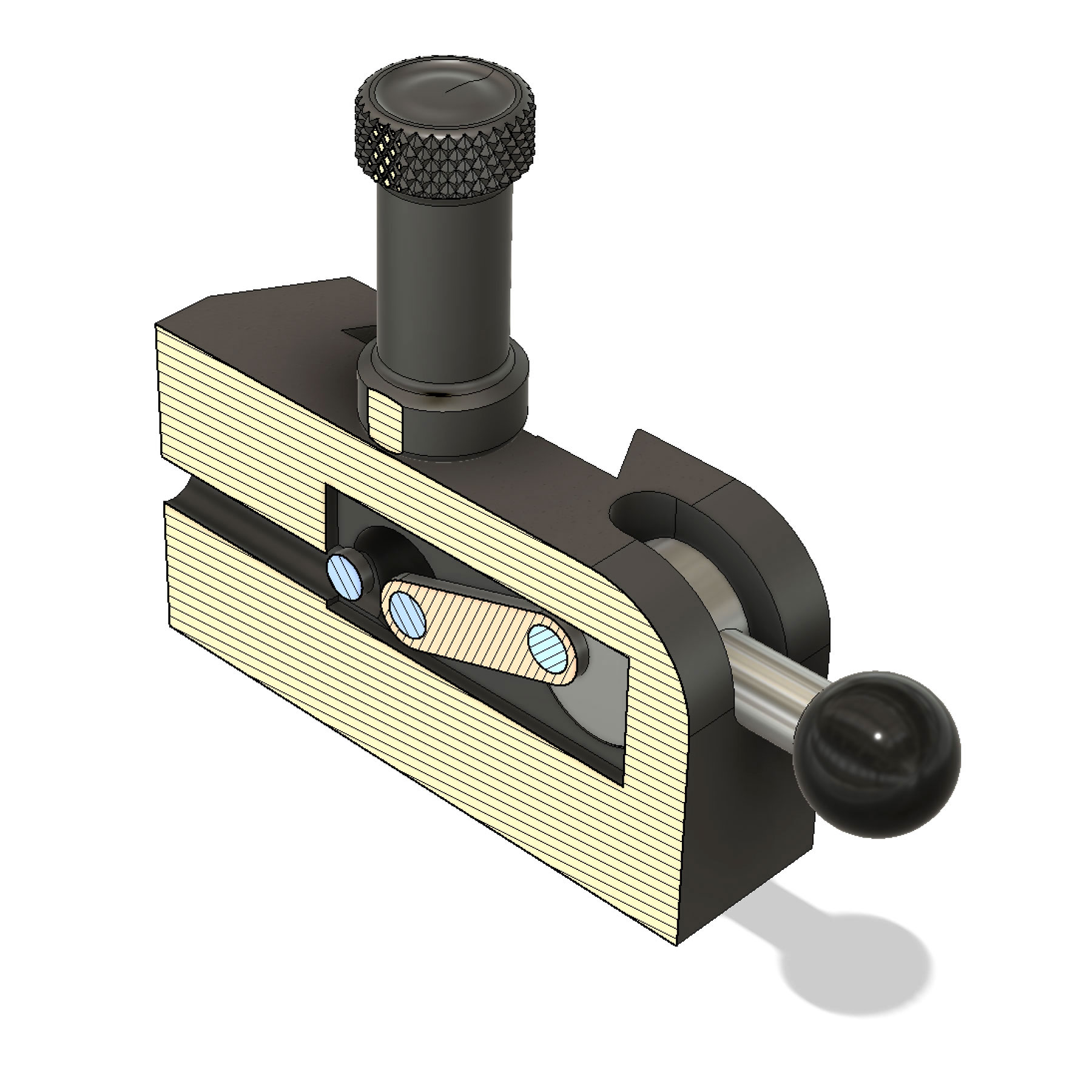
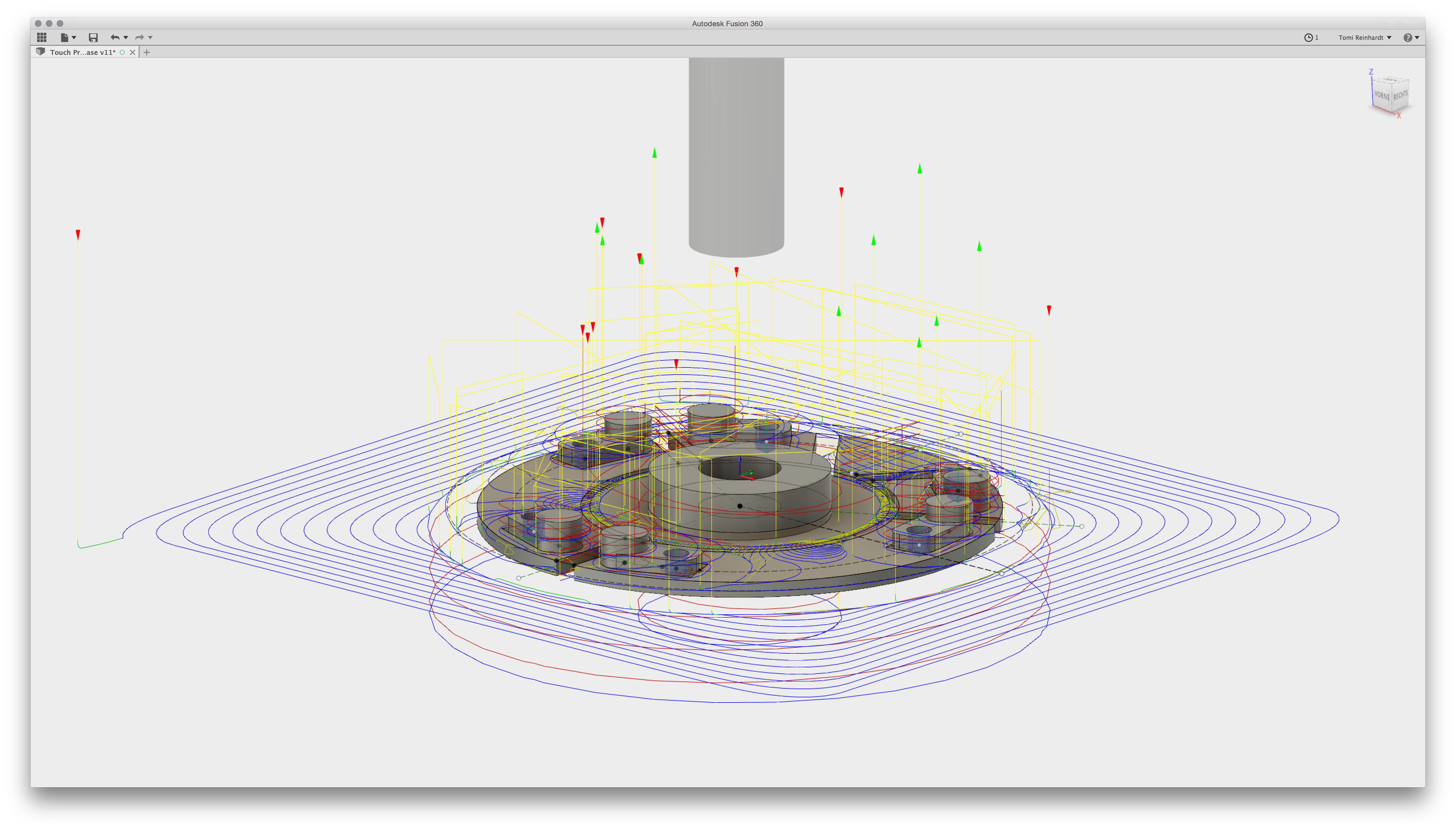
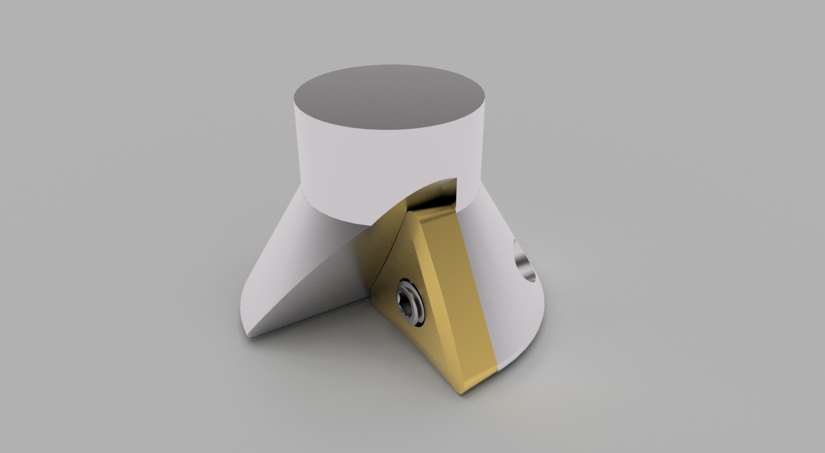
The first sectional view shows the lever mechanism in neutral position.

The through hole on the left is tapped on the end and holds the spring. The two blue circles next to each other are the pins on the slider – the last one from on the lever.

In neutral position, the spring-rod pushes the carriage and the lever back. The lever is in the upper position.


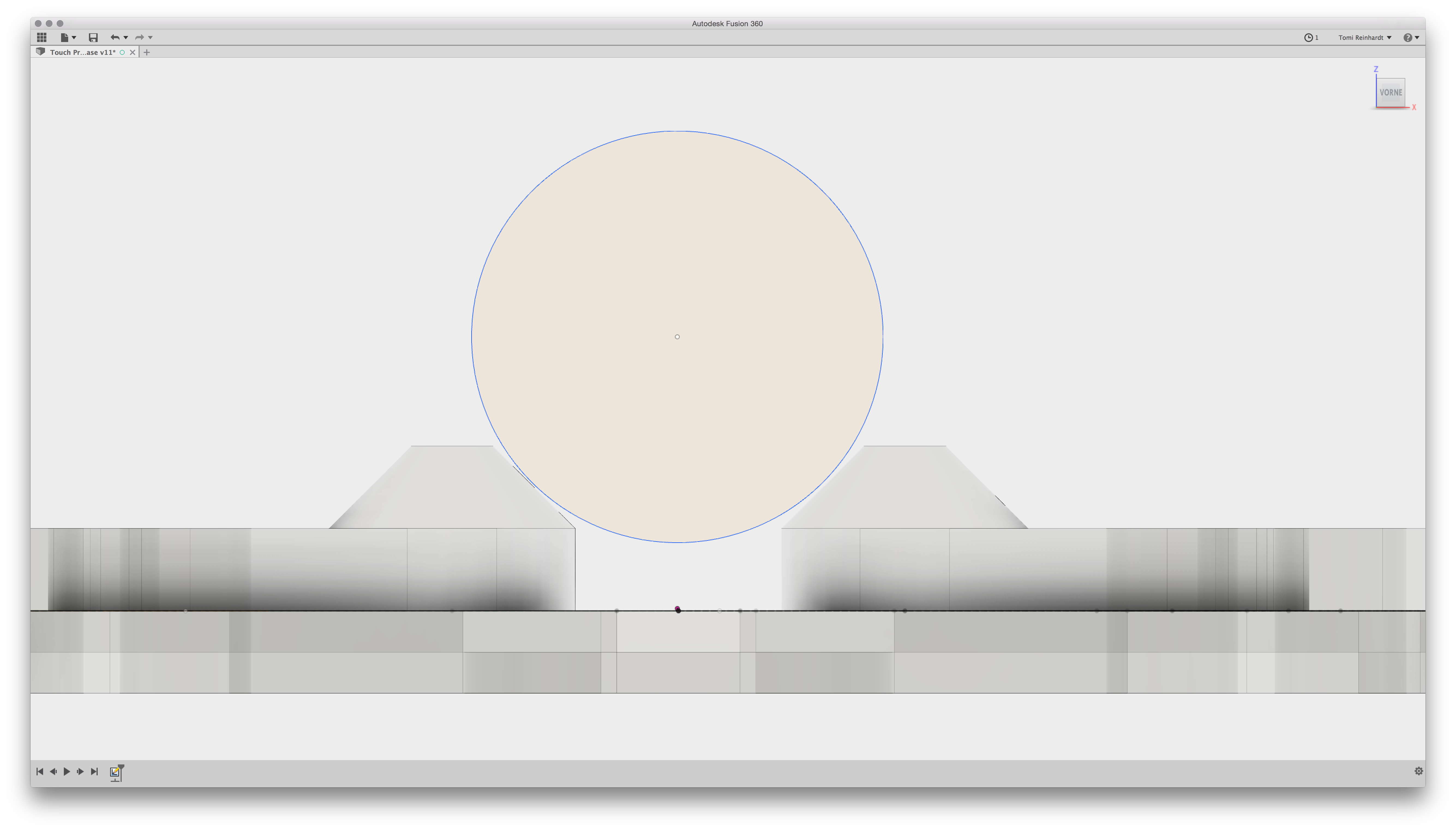
In the activated position, the angle of the link in relation of the lever circle is slight above the center. In combination with the spring tension, this latches the setup in an safe engaged position.

Desengaging the tool needs minimal action and force – as soon as the angle drops below the center of the lever, it’s retracted by the force of the pushing spring rod.
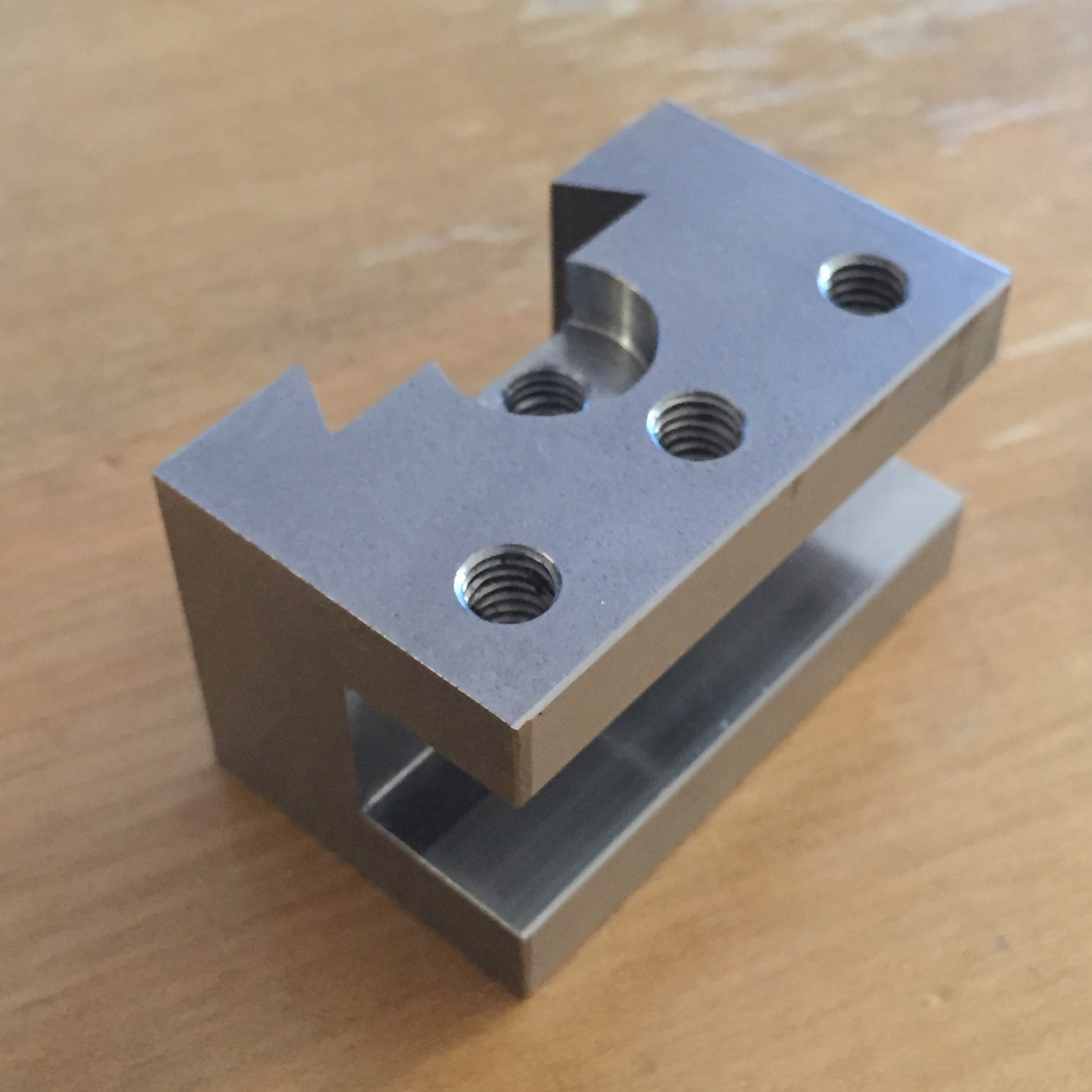
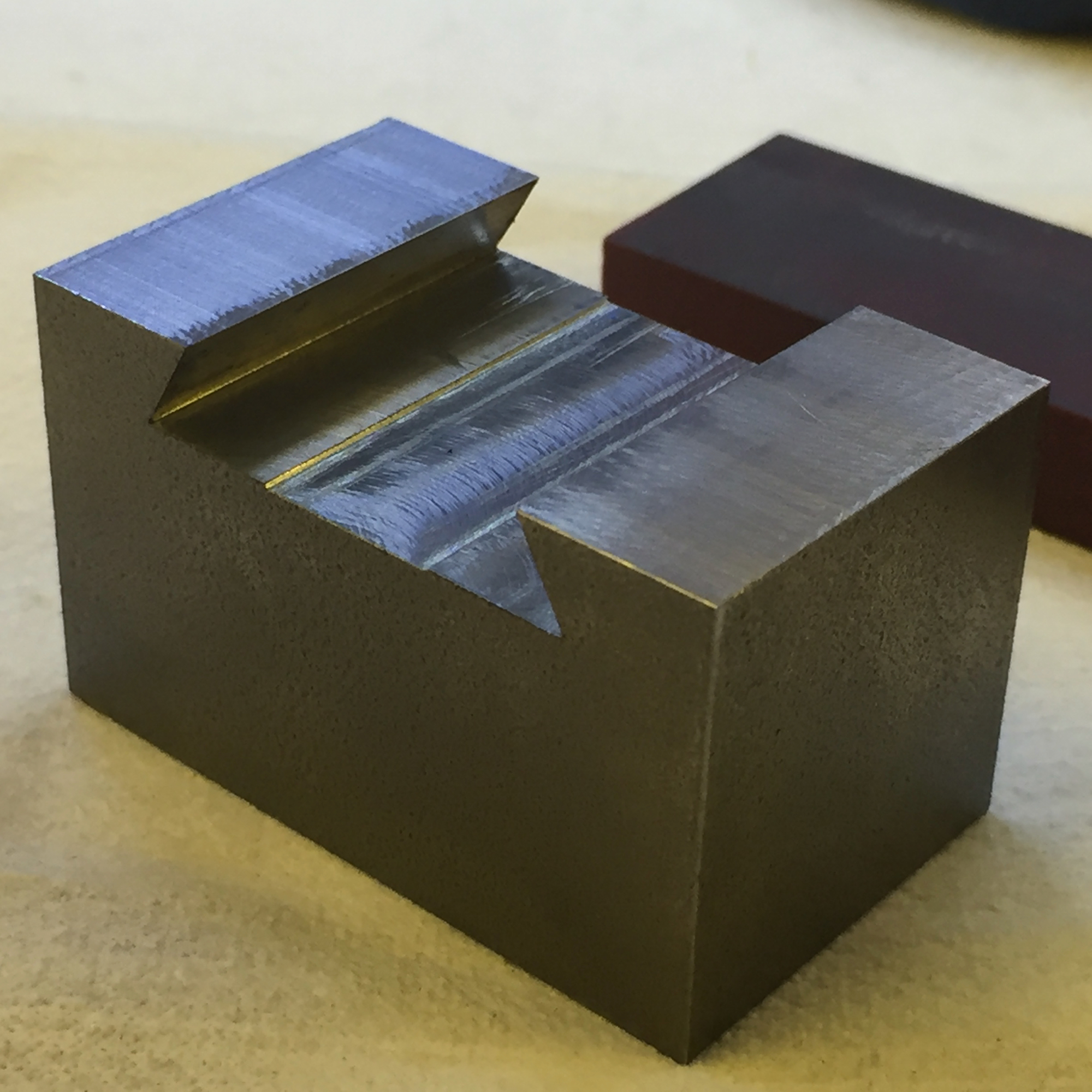
Making

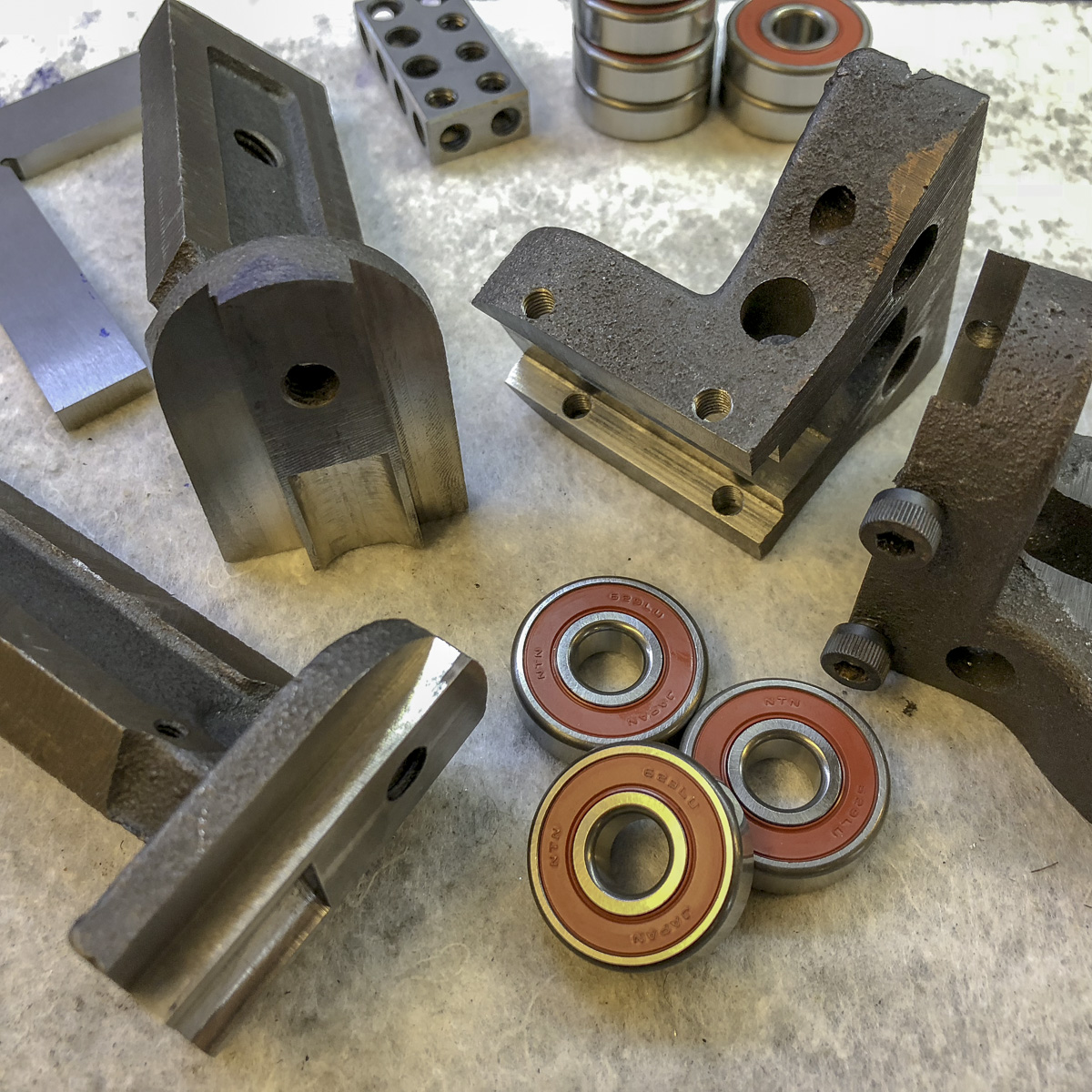
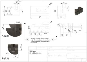
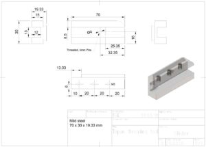
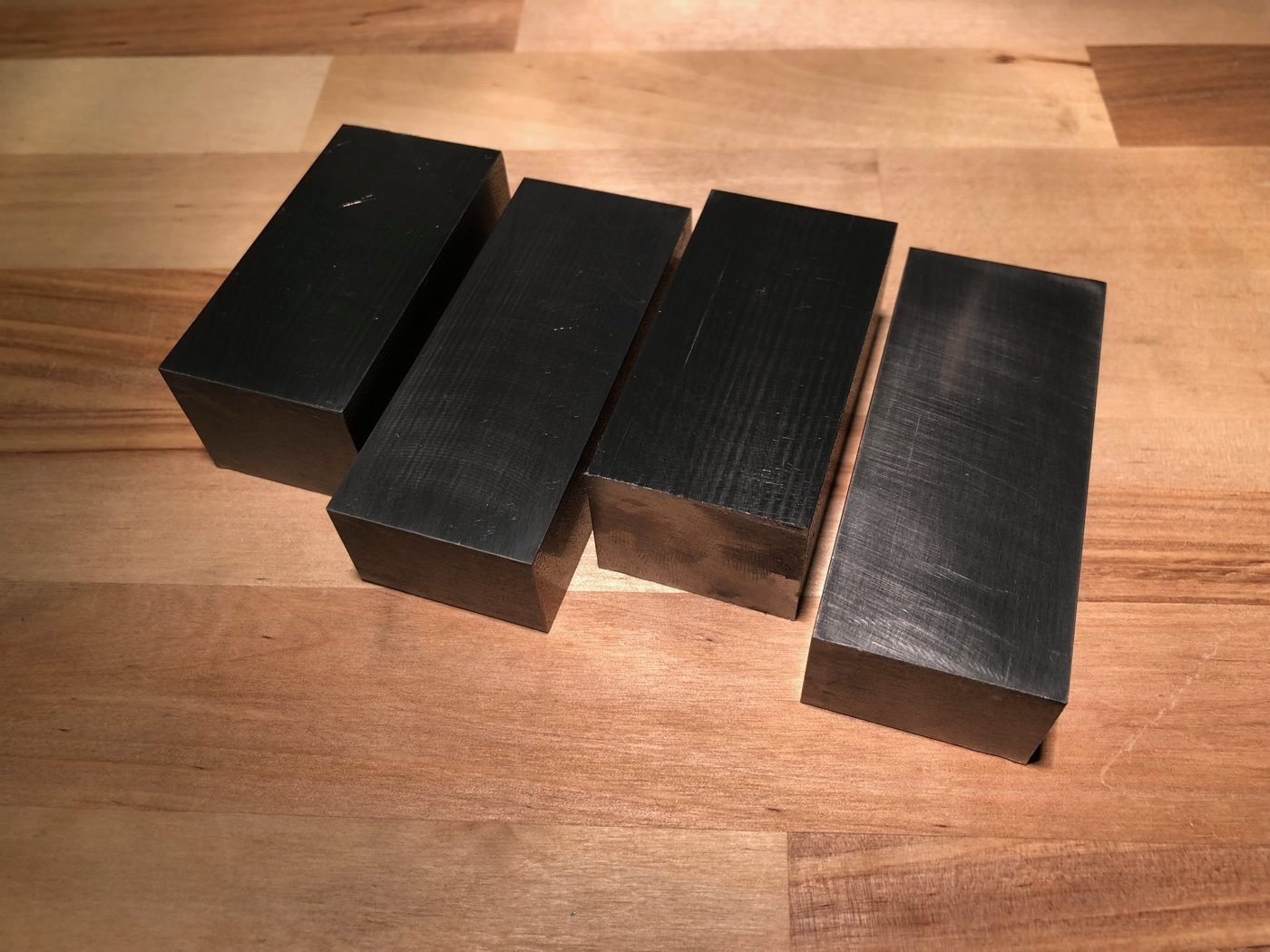
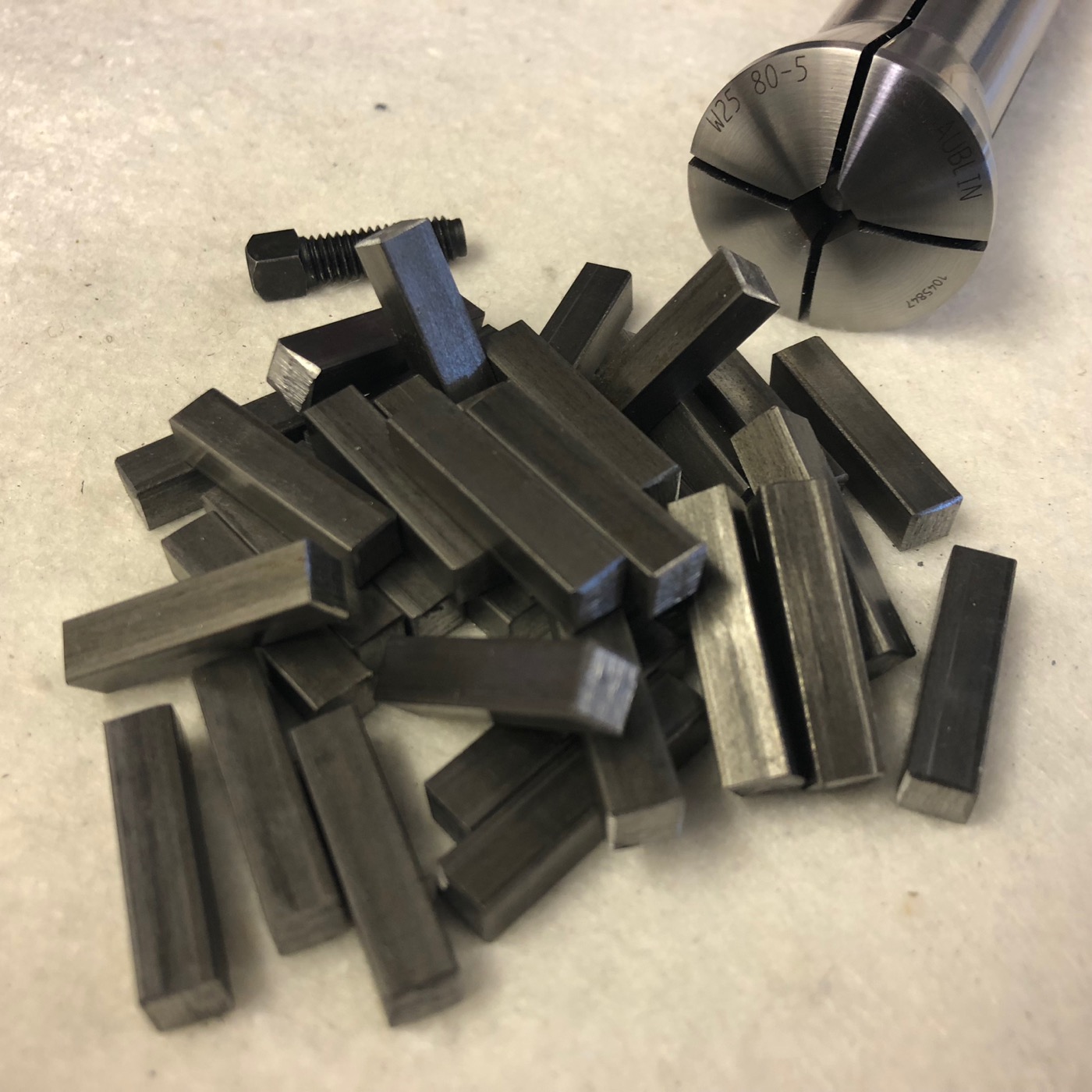
The tool is made of 1.0570 (S355J2+C, or in the USA: 1024). This is low-carbon steel and not really made for hardening (possible tough) – don’t know yet, if this tool needs to be hardened…

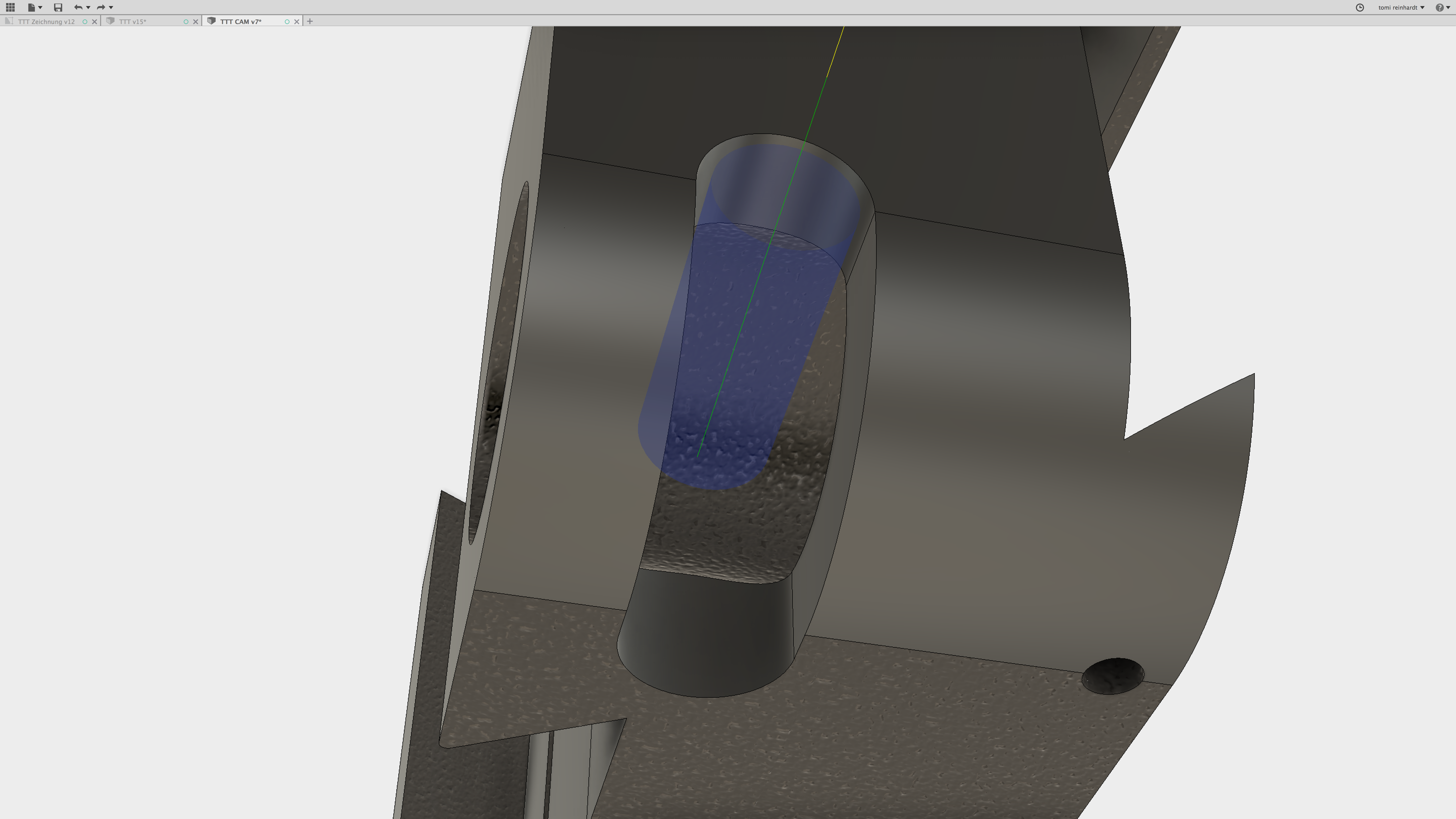
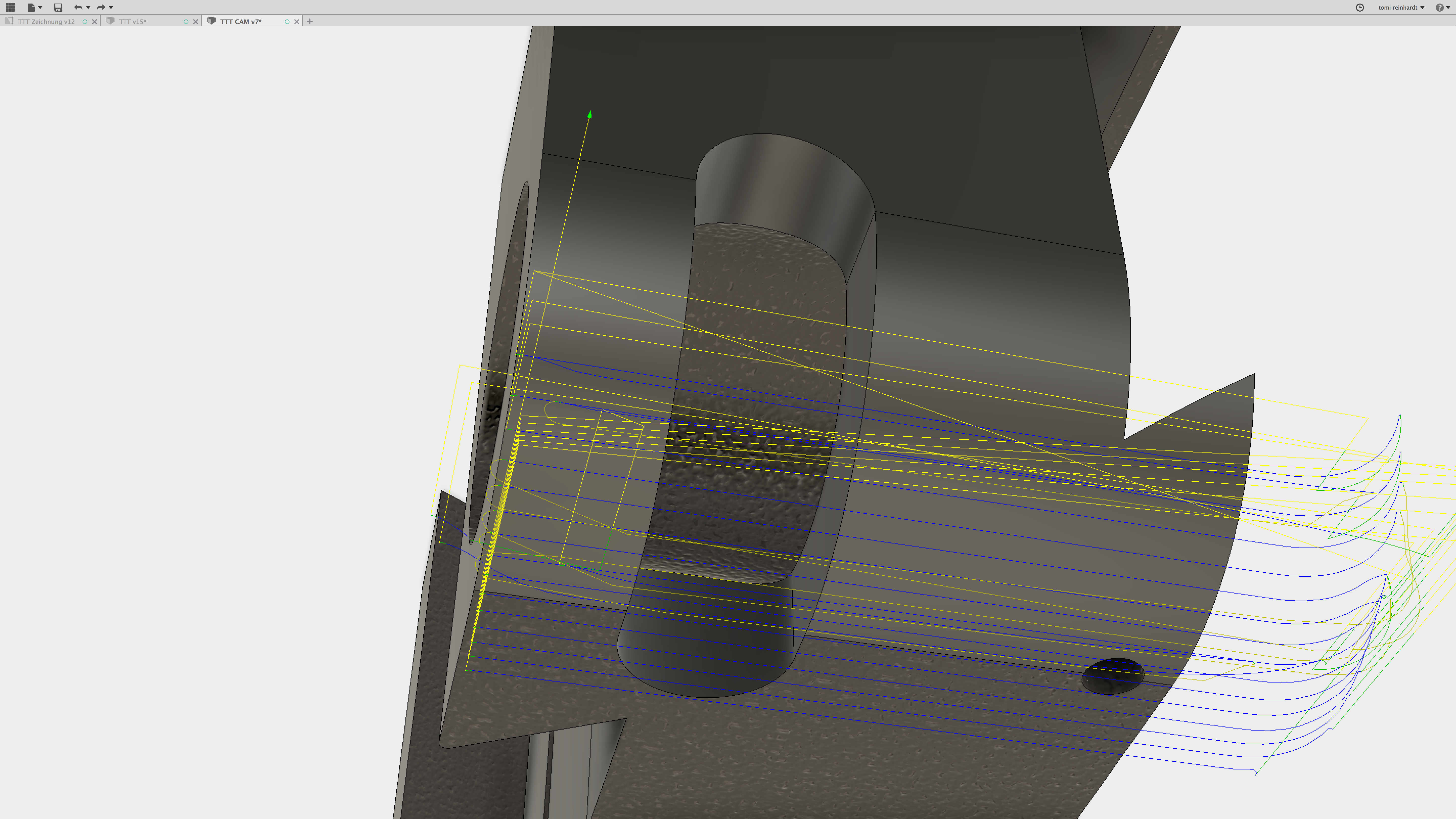
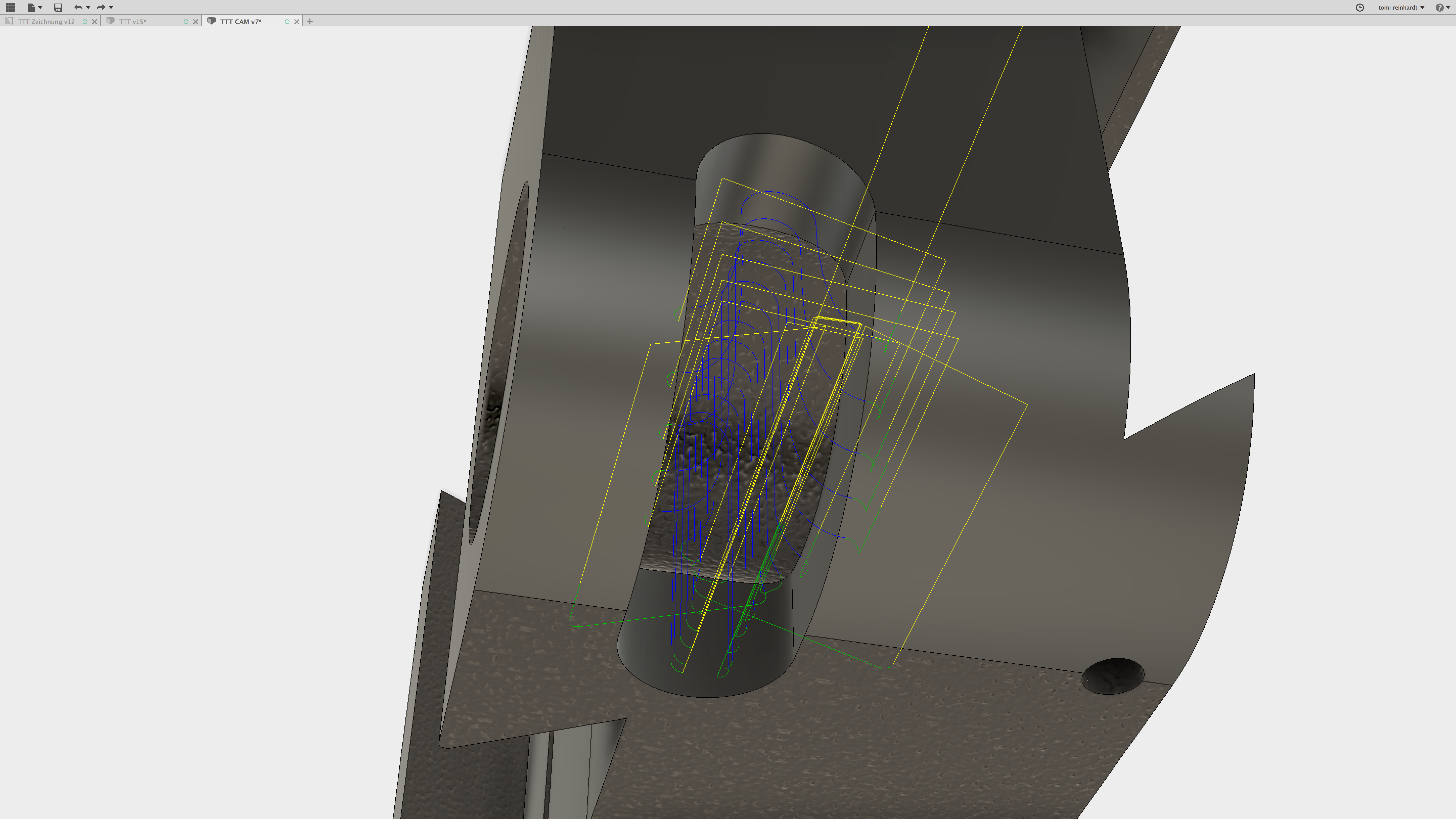
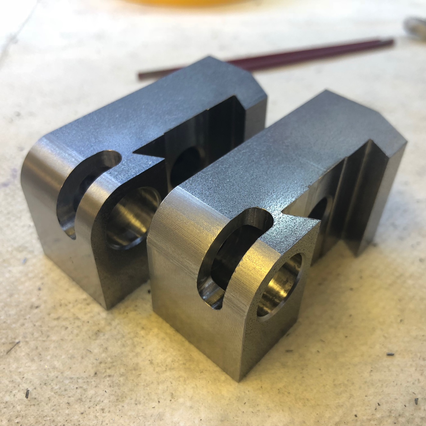
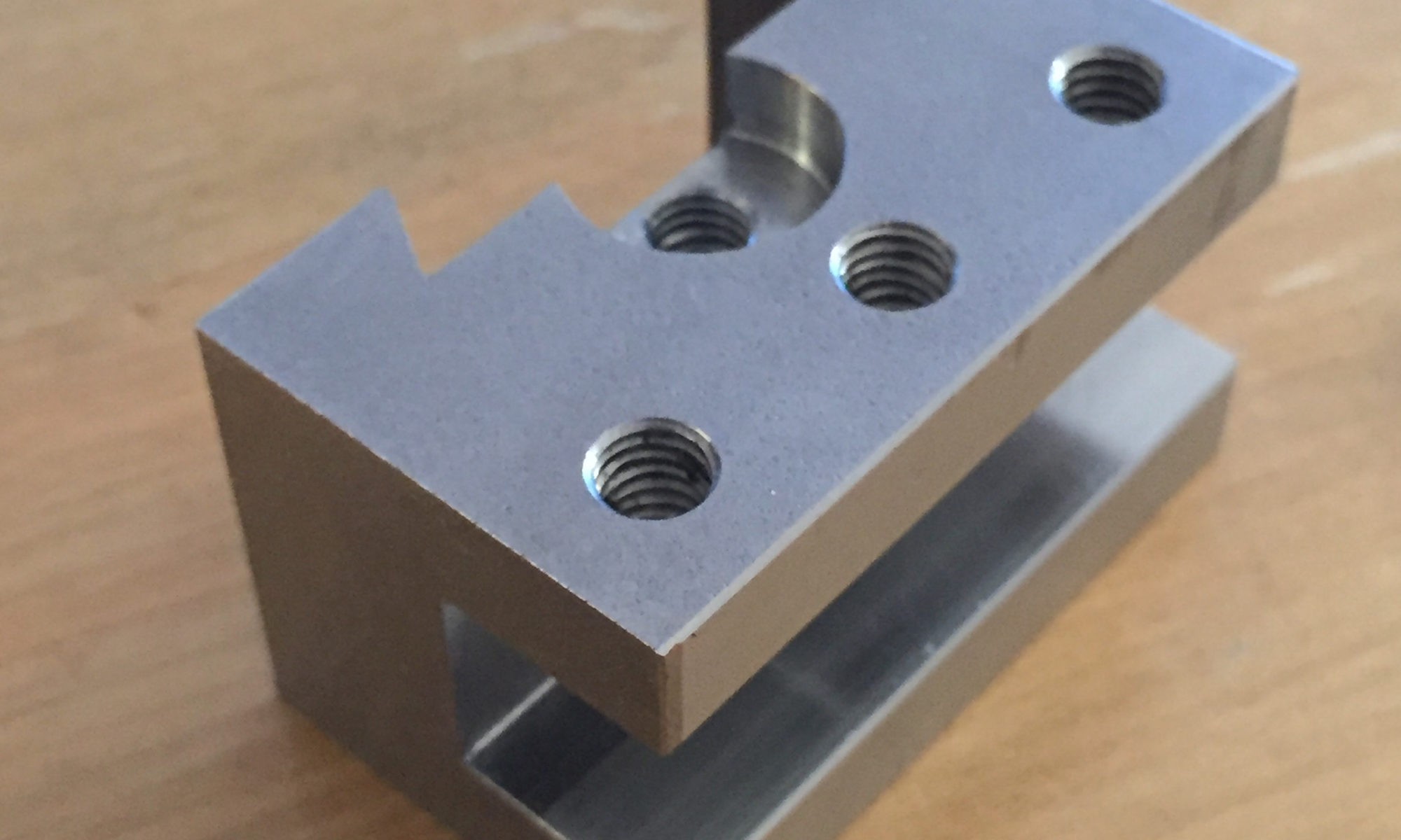
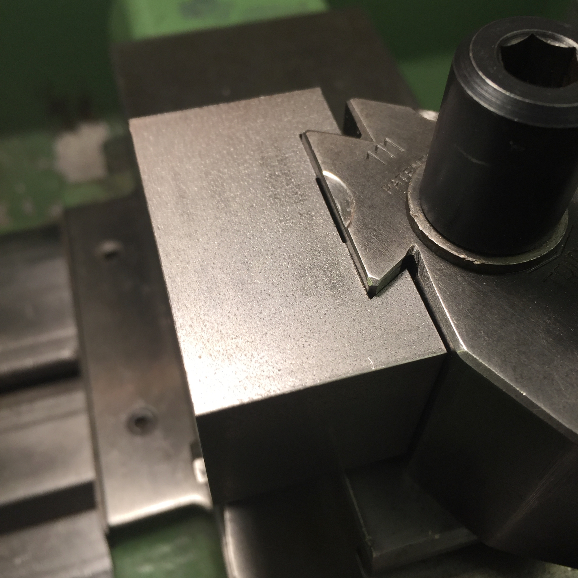
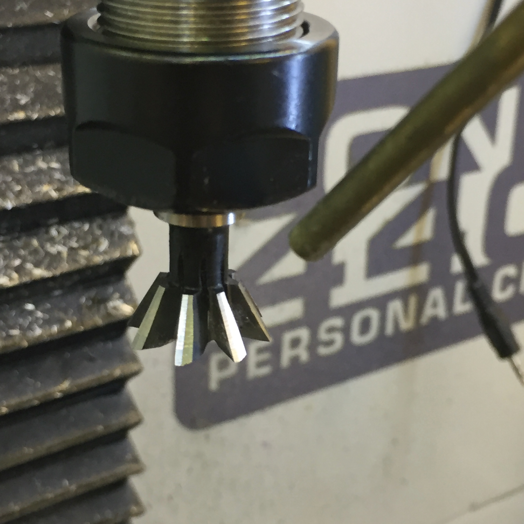
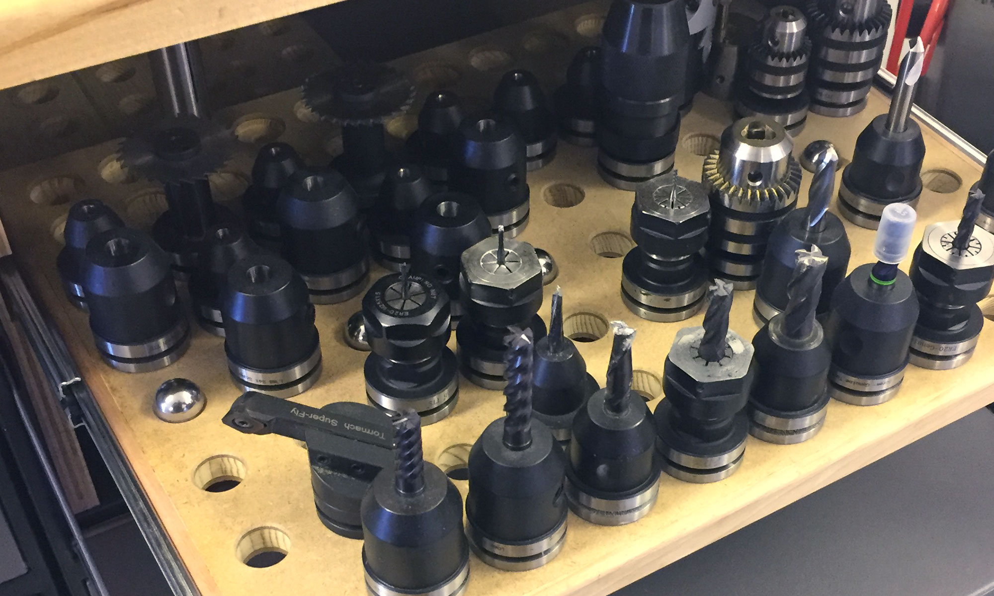
Most parts were milled on the Tormach PCNC440. There were tricky ones, like the dovetails, which need to be smaller than the ones of the back of the toolholder (btw.: yes, also the little version of the dovetail cutter showed on insta works like a charm), or the small cross-section for the lever, which needed a precise angle on the top as back stop. Some screenshots from the «lever side»:

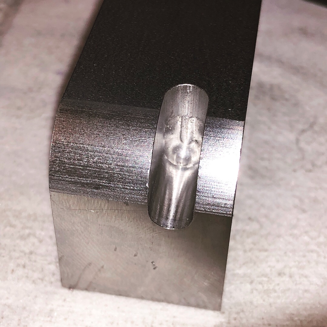
Another difficult part was the axe which connects the slider to the lever: even though it’s possible to simulate almost everything in CAD/CAM, I had to make another version – 0.3 mm longer. It worked perfectly, but in the neutral position, the slider poked out a little bit 😉 

After assembly, it turned out, that two pins on the slider was overkill. One is enough – with the benefit, that a stronger ball-point-pen-spring could be used.

Plans

For those who are interested in: here are some PDF-Files of the different parts which were made:

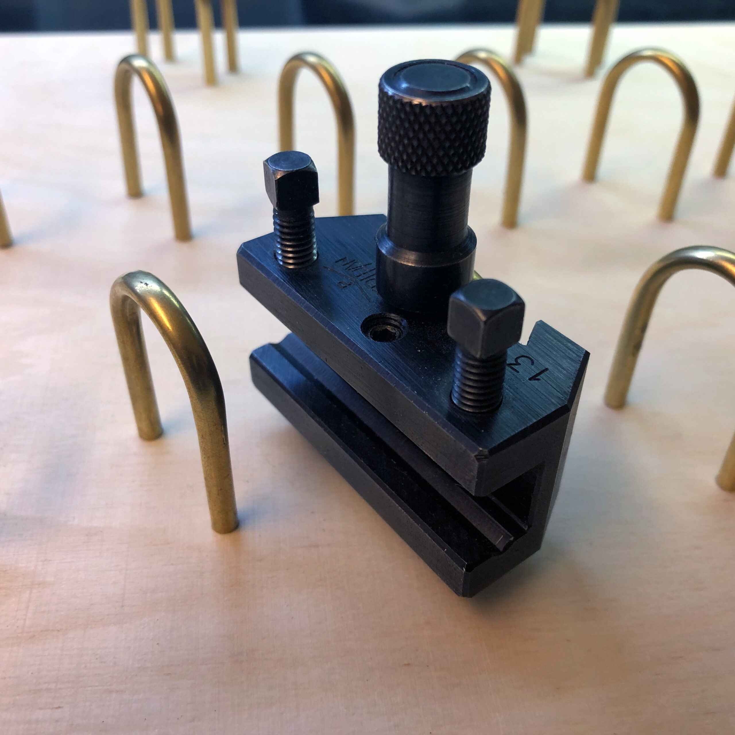
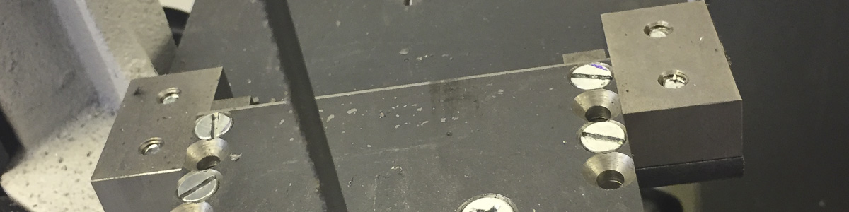
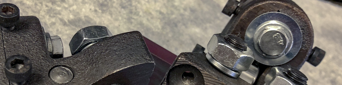
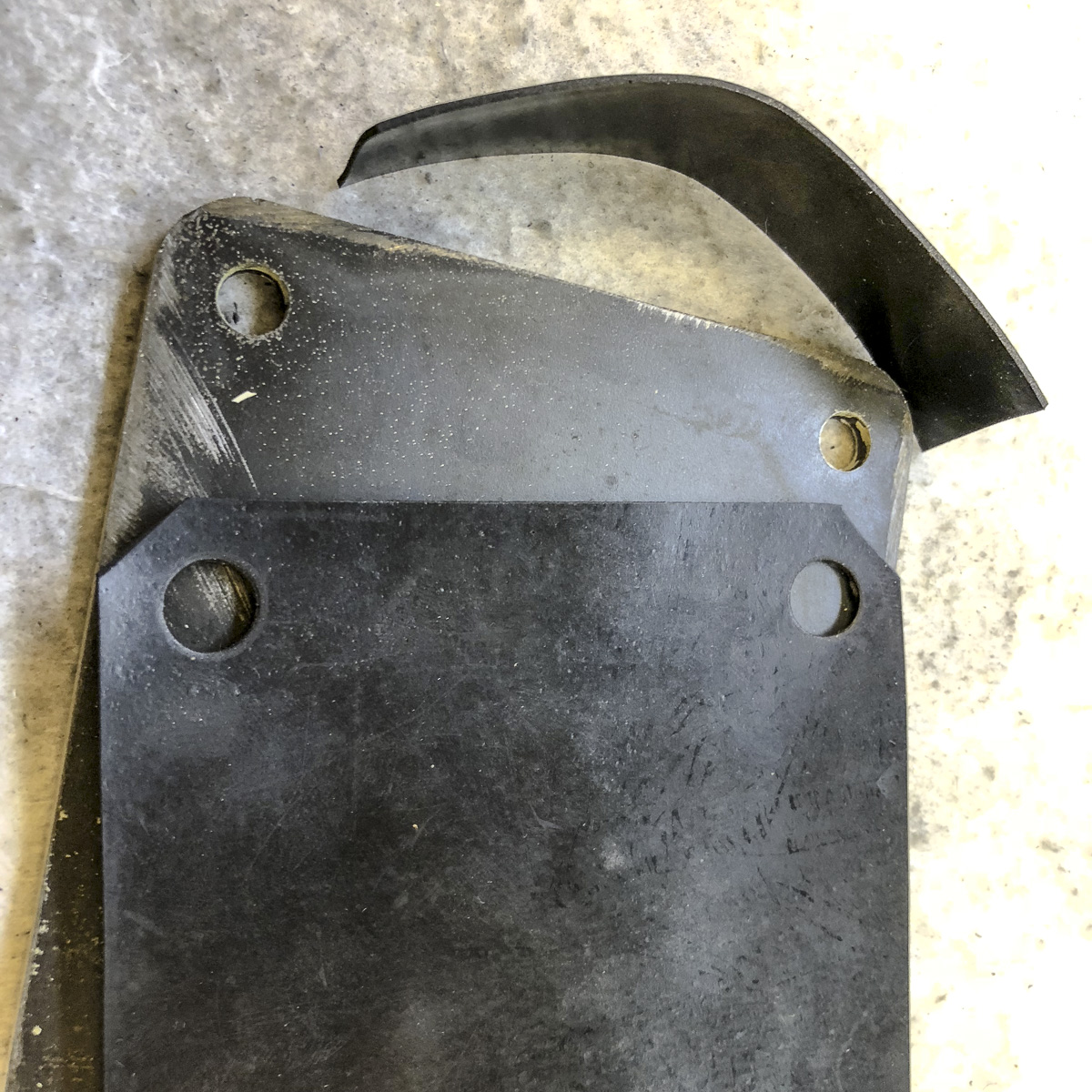
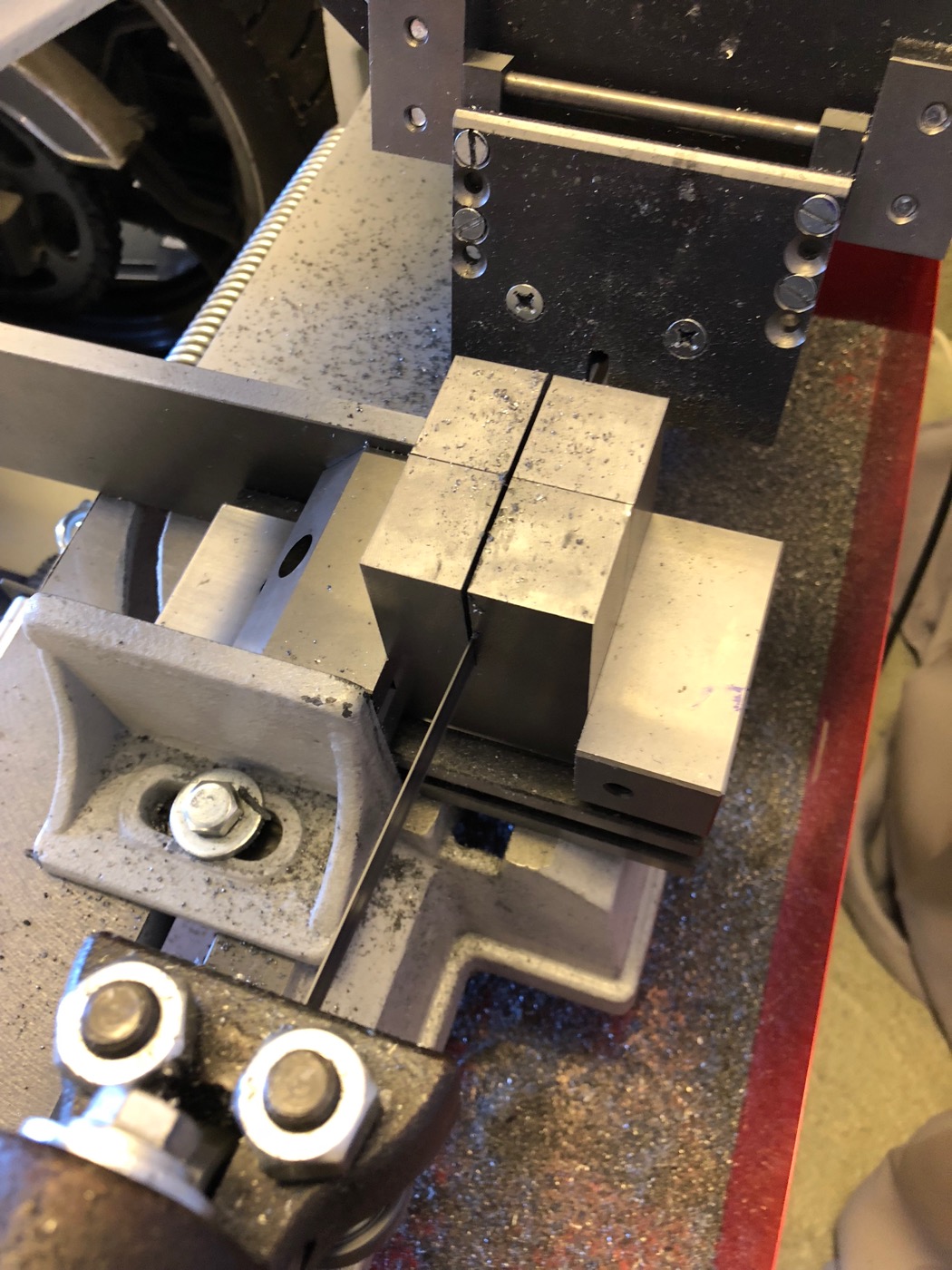
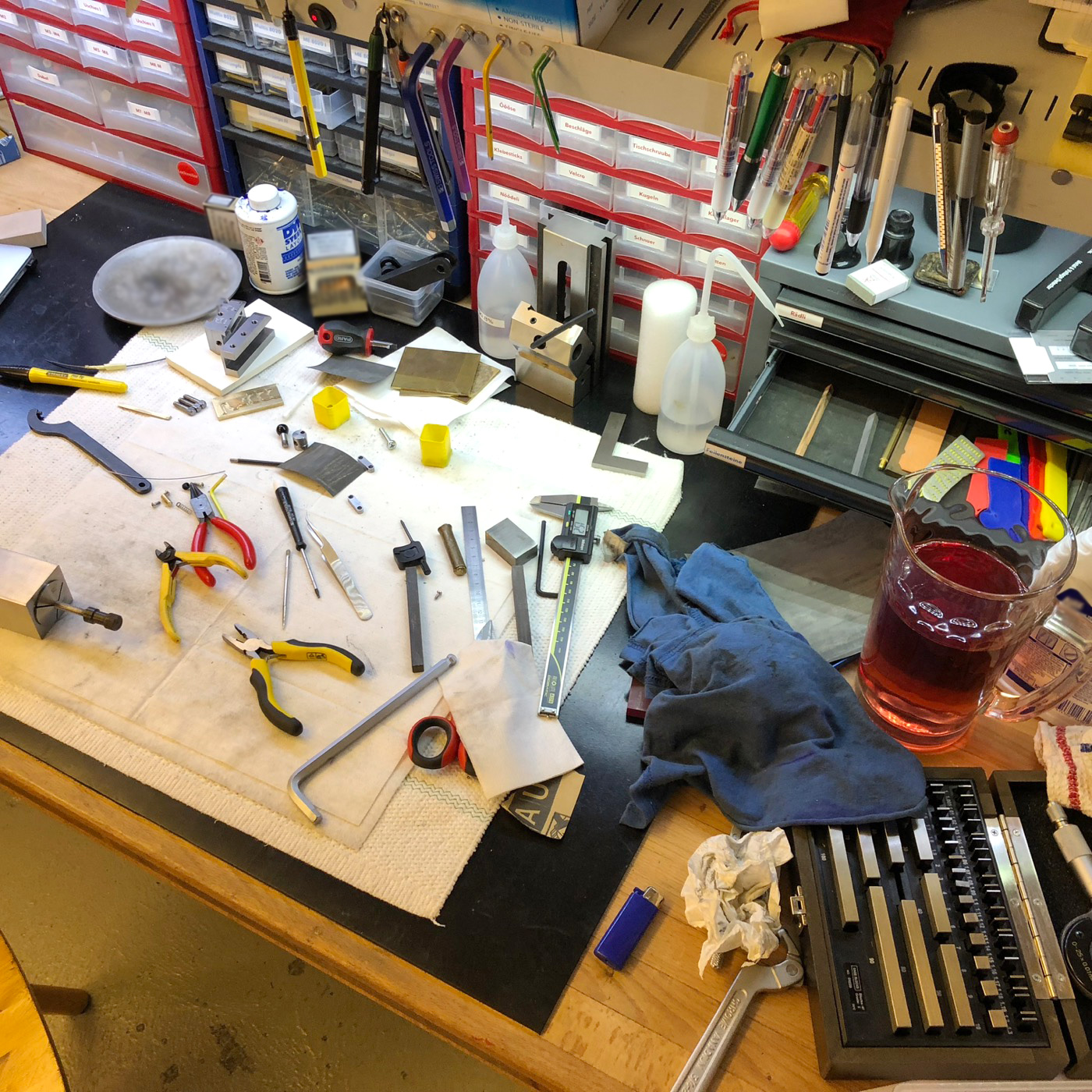
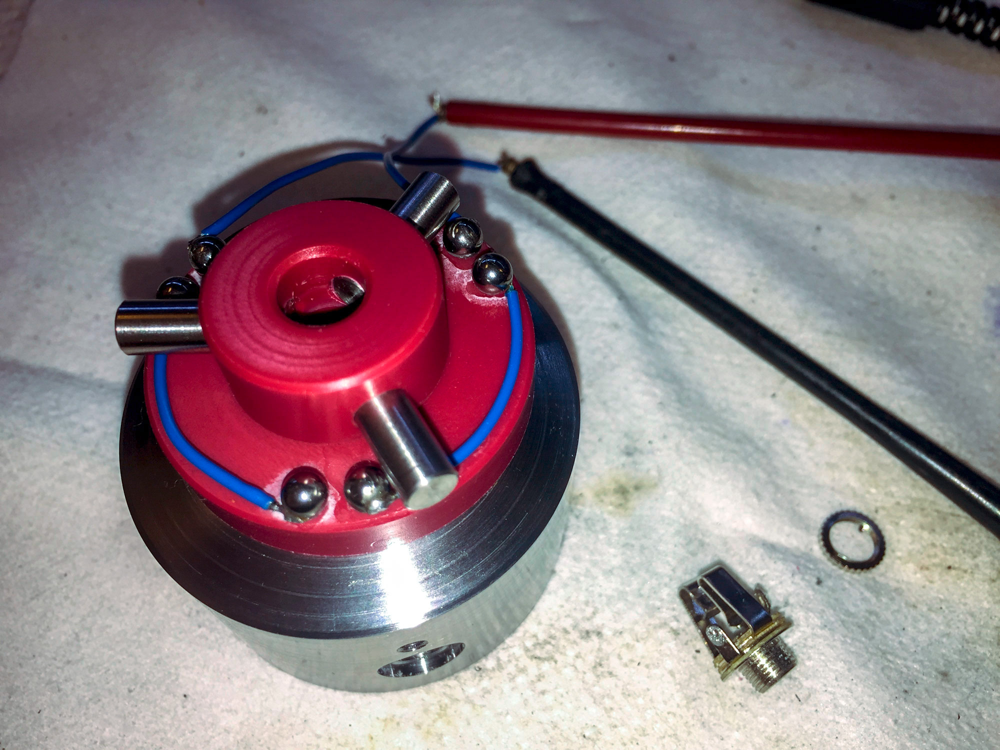
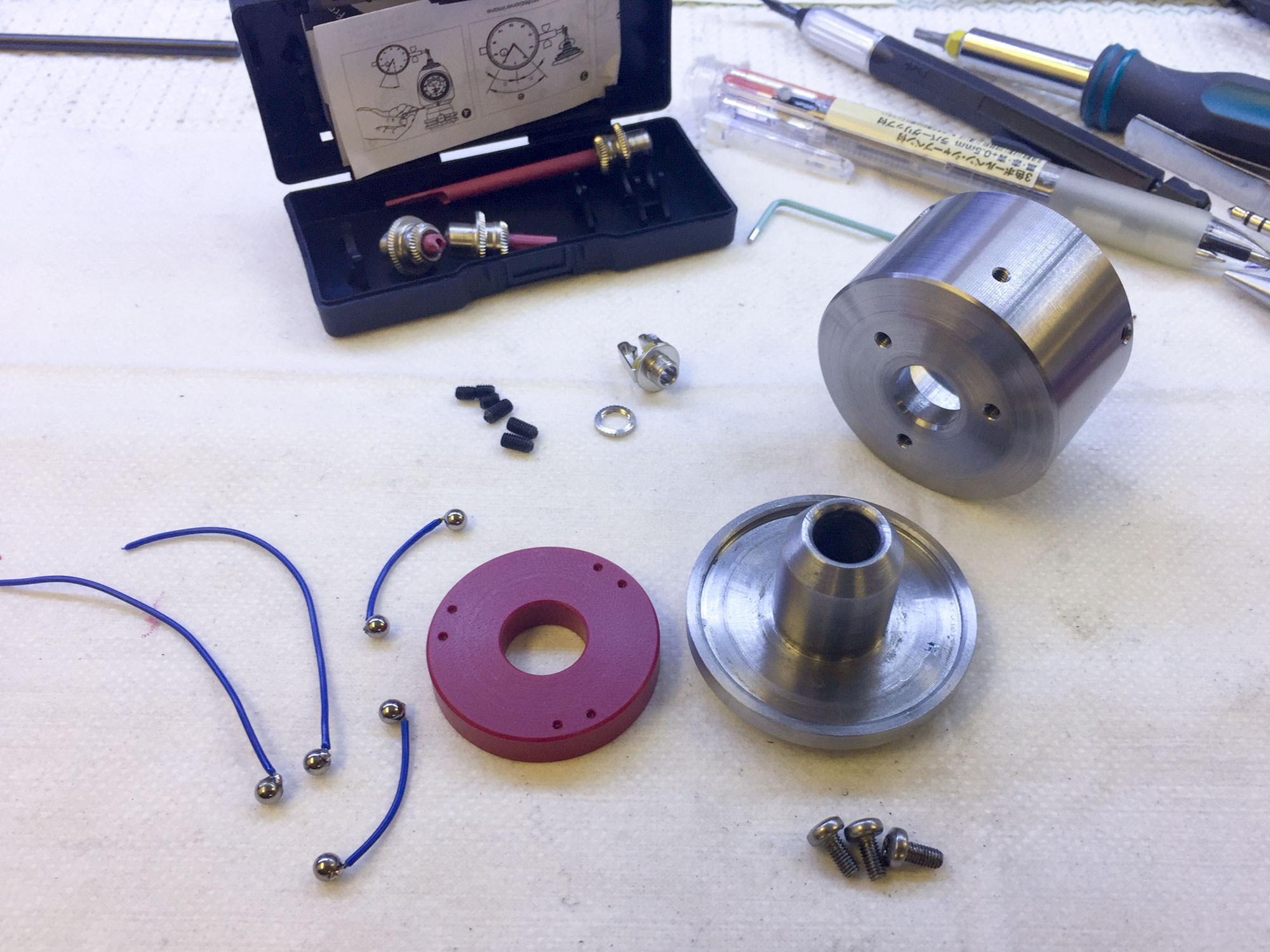
And some photos of the working in progress:
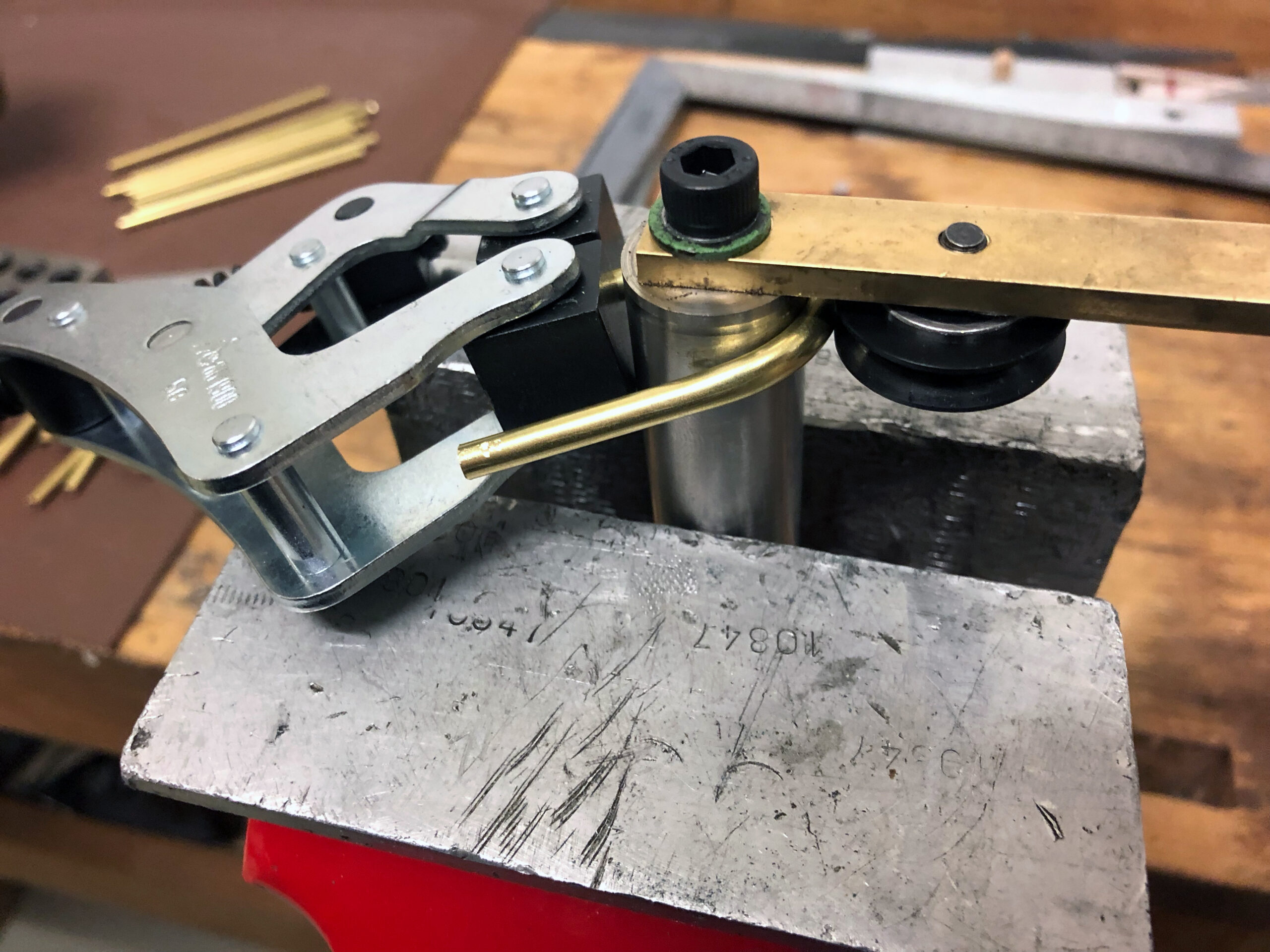
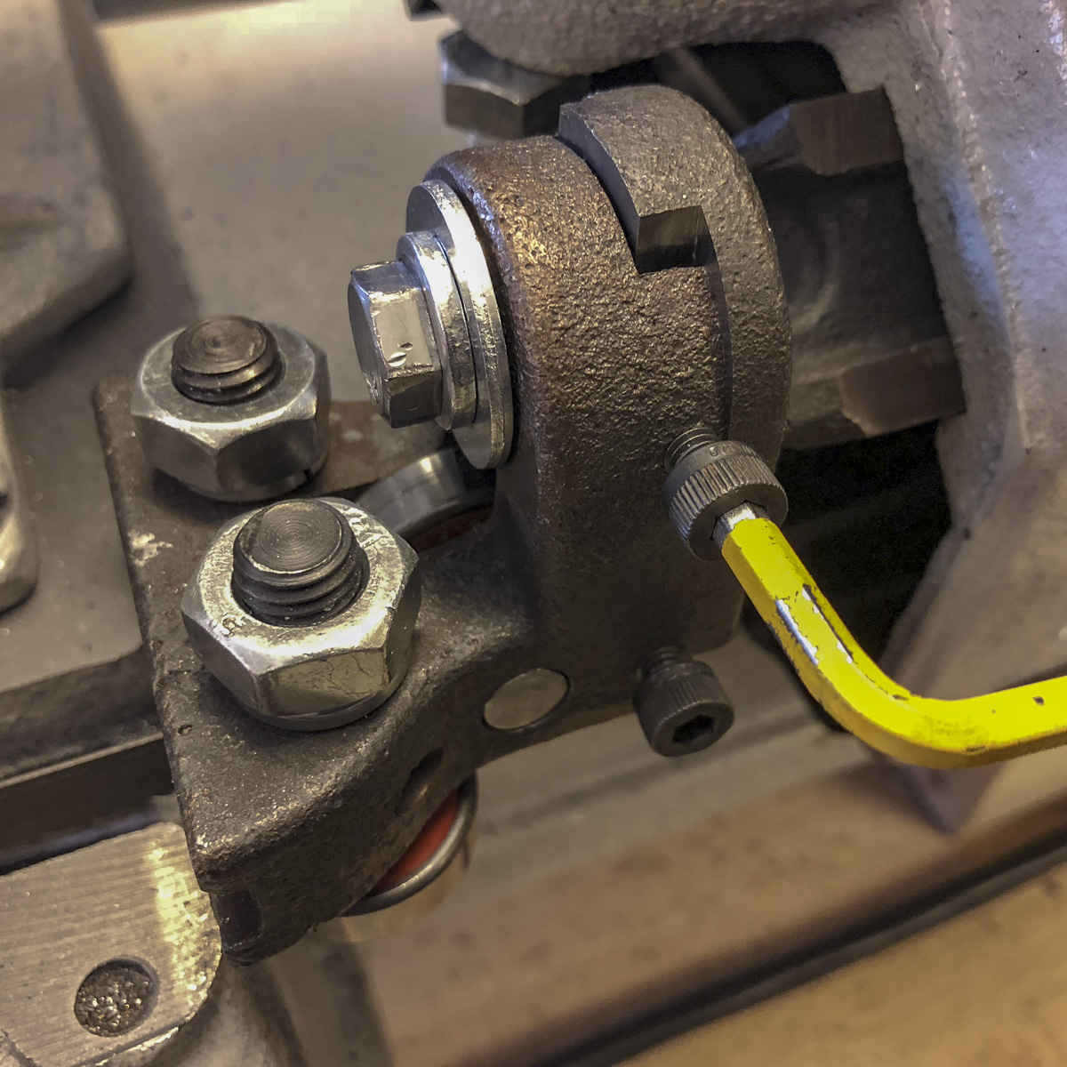
Using the tool

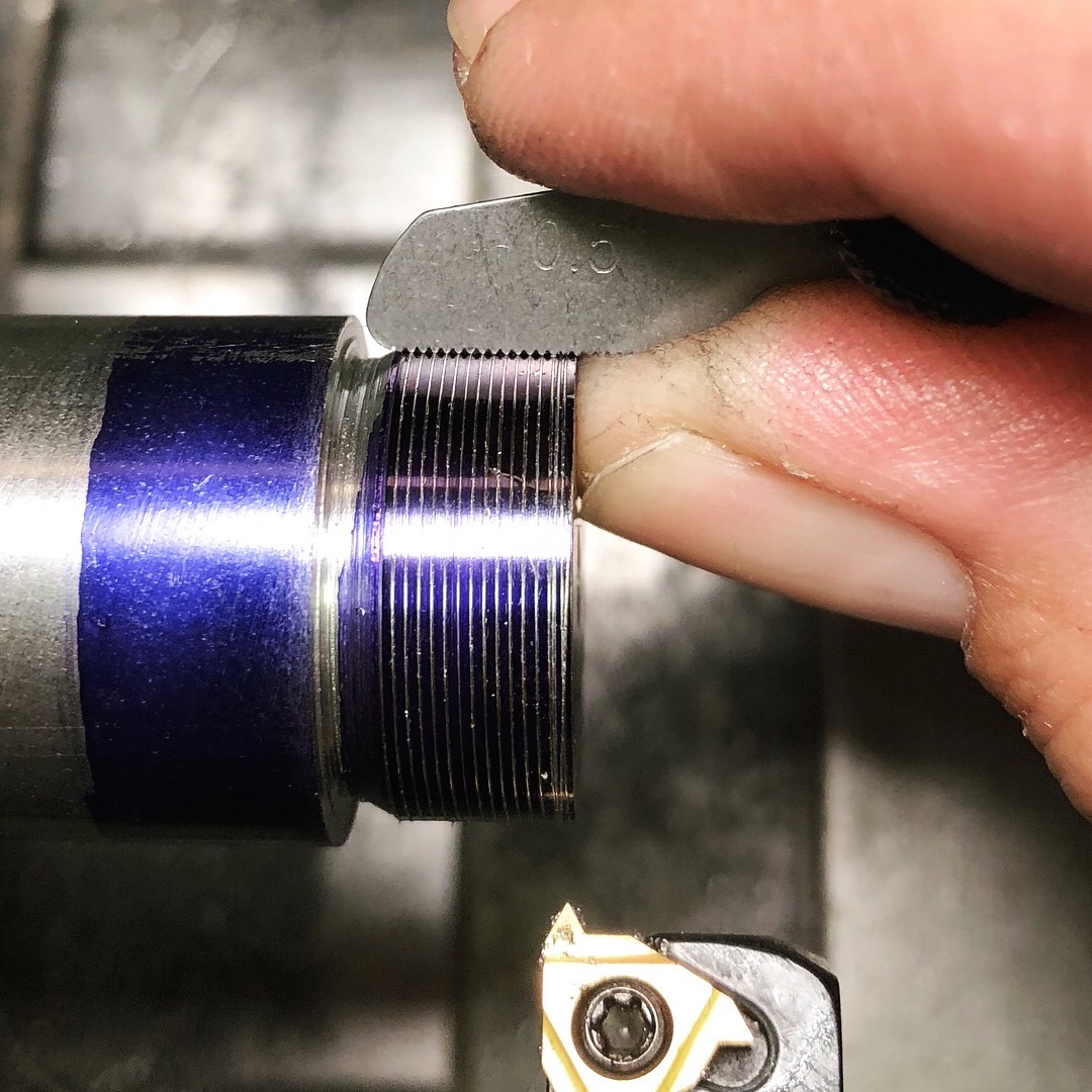
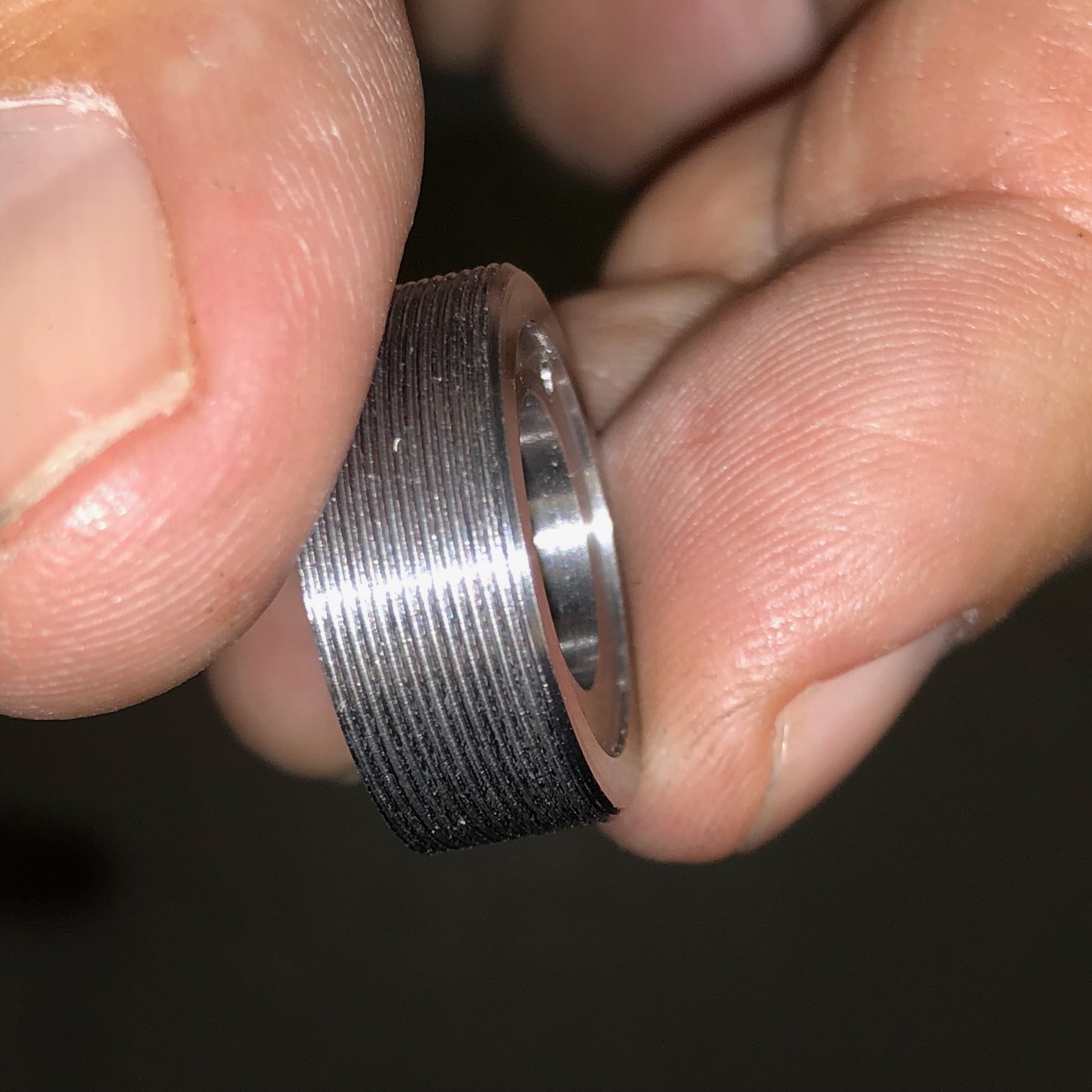
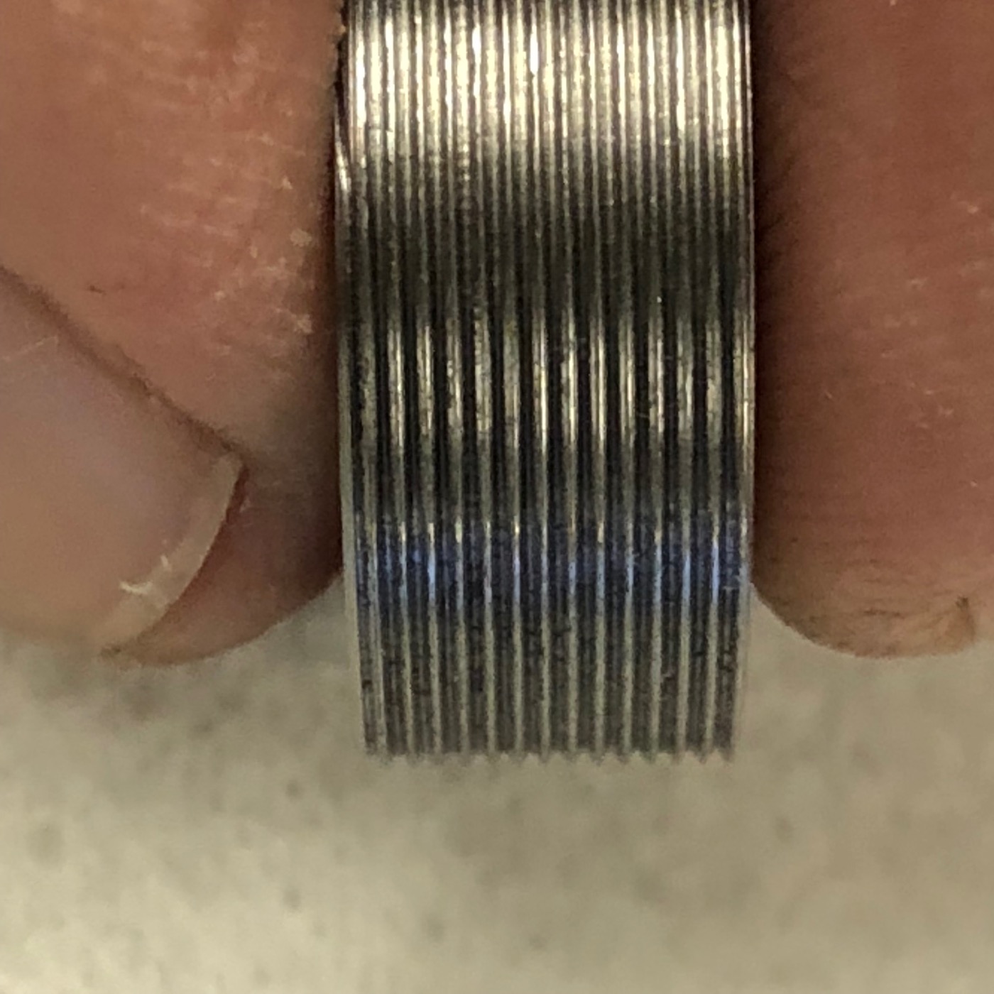
First: the tool works! It’s quite sturdy and won’t move while turning the thread. Though, you really have to set up «soulful» the force of the dovetail clamp. A too high clamping may block the carriage – a too low results in sloppy toolholding!

These images were taken from my next project. An M20-something with a fine thread. That was an easy task to do with this tool.


Power drawbar foot pedal mod

The power drawbar is a great add-on for the PCNC440. It eases the toolchange – which can get quite annoying the conventional way, after opening the spindle door, release the drawbar, …, tighten the drawbar and closing the case for the umpteenth time!

Yes, it’s a timesaver! But in my view, it has one drawback: the pneumatic push-button occupies one hand. And for a toolchange it’s really «handy» to have both hands available.

A foot pedal switch is a great idea. Even though there are pneumatic foot pedal switches, I didn’t wanted to hassle with long air pipes. A wire based electrical foot pedal switch is really easier to use – and to install too! The more so as there’s one in the shop I saved for later use – very simple, but sturdy, used on a punch press for years.

The bigger Tormach machines (like the PCNC770 or PCNC1100) have an electronic control circuitry for the power drawbar. Unfortunately the PCNC440 misses this option, but the needed information is on the net or can be seen on the pneumatic push-button:

  • 5 ports
  • 4 way
  • 2 positions Air Valve
  • the machine has a 48VDC- or 24VDC-output integrated (for the solenoid)

The solenoid air valve I found was an «Airtac 4V210». All in all about 20 bucks, some silencers and connectors included. Yet, the filter regulator lubricator (FRL) was set up later on – another 25 bucks investet in persistence…

The implementation was easy. The 24VDC-output (used for the water pump relais) has of course also the right values for a solenoid. The foot pedal switch was simply clipped in between.

The connector was placed between the 5-pin-connector of the height gauge/passive touch probe and the probably future expansion slot of the 4th-Axis. The toughness of the body housing is impressive by the way!

Conclusion

Besides of the power drawbar being really «handy», the footpedal activation is really fast and comfortable. You can remove the actual and insert the next tool within seconds – really a big timesaver.

Open issue and warning

Even though the footpedal is only «primed» if the machine is powered – it’s always active while it’s powered! This means, that a misstep while the spindle is turning could be fatal and dangerous. Please take precautions if you think about making such a mod – everybody is responsible for it’s own and the health of others around!

I need to dig deeper in the controller scheme – I’m quite sure, that there’s a possibility to deactivate the solenoid, while the spindle is turning…

Tripan Toolholder

I have a Tripan toolholder system on the Schaublin-102VM lathe. It’s an «old school» quick change system with adjustable height and quite a good clamping capability. I really like the quality and the versatility this system offers – and it matches perfectly on this lathe.

Just because I live nearby where it was produced and probably mainly used, this doesn’t mean, that we could get them cheap – they are still quite expensive (we get them unused for about 85€ p.p.). Therefore and because I’d like to have a better feeling for machining mild steel, I wanted to make a  run of 10-12 of them. Right: about a dozen – a mechanical artist on Instagram about that fact (Thanks Robin):

robinrenzetti Looking good, no such thing as too many tool holders. 💪👍👌

CAM

I own some original toolholders – and there are some plans with measurings on the net. So, making a CAD-file out of that material was an easy task. At the moment, my favourite CAD/CAM/Rendering program is Fusion360. Take a look – you can manipulate the image yourself:

Prototyping

I always like to test some setups, materials, speeds’n’feeds, etc. – even too in the production run! The prototype means the previous step for me: a first physical output, which you can move in your hands and study directly on it. Even though CAM and CAD are quite sophisticated these days, they won’t beat the physical output.

The first prototype turned out well. The dovetail cutter won’t take a whole production run, and there were some «design issues» – but technically the «proof of concept» was done…

CAD

For machining this little piece, three different setups were needed. If you make a production run and have the stock-pieces in the same dimensions, you can ease your life by indexing them in on the lower back inset – this way, you don’t need to bother about heights (you set them in the CAD-program). The mentioned setups are:

  1. Back face – with the dovetail, where the toolholder is clamped
  2. Top face – with the three clamping, and the height adjustement screws
  3. Front face – the one where the tool is mounted

Back face

As mentioned above, on the first try I noticed, that tool wear would sooner or later be a issue on the production run. The dyi-dovetail-cutter solved the problem (and lasts till today – after a dozen of dovetails milled).

By the way: the width of the dovetail isn’t that critical in my opinion. On the drawings I mentioned before, really tough tolerances are given. But finally it defines the way the base lever (on the Tripan 111) has to travel – nothing significant for working with it.

The back surface (image above: on the top)

… not finished yet. To be continued…

Merken

Merken

Merken

Passive Touch Probe

For some work, a touch probe appeas to me as the right approach. The most obvious here is the indexing of circular objects like holes or round stock – where one should measure one of the axis twice to get the right middle point.

The tools which are sold are quite expensive. Sure, it’d be precise – but I think with the right concept, it’s possible to make this (otherwise simple) mechanic accurate for my needs. 

The main concept consist of a closed electrical loop with three gaps, which are bridged by rods attached to the probing tip. The CNC notices the input as soon this closed loop is interrupted. Here one of my attempts which illustrates the idea behind:

Six setscrews were integrated in the housing – to calibrate the position and the orientation of the probe tip. Three on the bottom to balance it to the vertical of the CNC-Machine, and three on the side face to bring it in line the the arbor. Take a look to the following image. The top of the case was turned separate with a kind of TTS-collet. It’s mounted to the bottom part – on which you can see four of the six setscrew-threads and the hole on the bottom where the probe-tip-assembly gets through. As probe tip I used some broken ones from the Haimer 3D Sensor – therefore I don’t need a new type and can make some probe tips myself (that’ll be a separate post).

The red plate which is placed inside of the bottom part and the wiring with the 3 mm balls soldered on them is not the final solution. This was the complicated part of the project!

The used material reaches from polyoxymethylen (POM or Delrin) to polyvinile chloride (PVC), brass and copper inlays. Exept the first on the top left, all of them has issues with either the bearing ball (try once to solder them 🙂 or the mounting of the whole assembly (POM and PVC really hardheaded to glue).

The solution I’ve chosen is the milled brass type assembly mounted on «a kind of wooden» base. This version is solid and shouldn’t deform itself – but to be sure: time will tell.

The model and the G-Code for the milling machine was generated in Fusion 360. I milled it directly glued on the «kind of» wooden base – if the glue’s cured correctly, the part shouldn’t break.


This way I got two basic advantages: probably the milling machine is more accurate than glueing some stainless-steel-bearing-balls and it’s really easier to plan such an assembly with gaps being bridget with some rods:

So there we go! The finished assembly mounted in the base and wired on some standard 3.5 mm headphone jack which leads to the CNC-machine:

First test: the probe works fine. Don’t know yet about the accuracy, I need to dial it in and do some calibrations first. But I’m already satisfied, that the concept works and that the probe tip doesn’t get crushed in the first tries…


Additional edit after setup and adjustment

The adjustment is very easy to do in the Pathpilot software.  With a little patience, it’s possible to get close to some hundrets of milimeters, which is enough accuracy for my daily needs. Here you can see the output while adjusting it:

Patience! It lasted until 4/100 mm for me 😉 

The usage is simple, but for my person: not as fast as the Haimer. At least for the standard setup – for dialing in prepared stock or holes or such things, this probe will still be my first choice!

Merken

Merken

Merken

Dovetail cutter

For my Tripan-toolholder-project i needed a 60° dovetail cutter. I got one which worked really great with the prototype:

After inspecting the work and the tool, I saw a beginning wear in the tool. Those tools are to expensive to get them stub after 2 or 3 parts. So, I thought about an indexable tool – but they are even more expensive than the solid ones! Consequence: make an own one. Continue reading “Dovetail cutter”