For some work, a touch probe appeas to me as the right approach. The most obvious here is the indexing of circular objects like holes or round stock – where one should measure one of the axis twice to get the right middle point.
The tools which are sold are quite expensive. Sure, it’d be precise – but I think with the right concept, it’s possible to make this (otherwise simple) mechanic accurate for my needs.
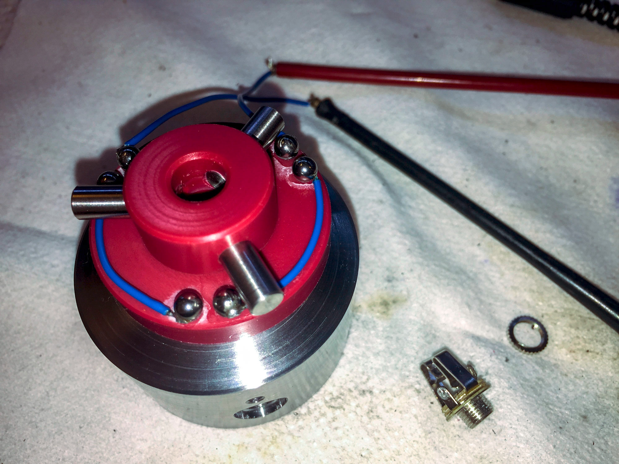
The main concept consist of a closed electrical loop with three gaps, which are bridged by rods attached to the probing tip. The CNC notices the input as soon this closed loop is interrupted. Here one of my attempts which illustrates the idea behind:
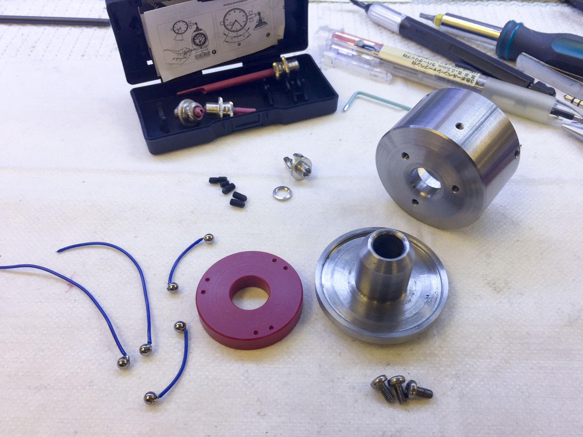
Six setscrews were integrated in the housing – to calibrate the position and the orientation of the probe tip. Three on the bottom to balance it to the vertical of the CNC-Machine, and three on the side face to bring it in line the the arbor. Take a look to the following image. The top of the case was turned separate with a kind of TTS-collet. It’s mounted to the bottom part – on which you can see four of the six setscrew-threads and the hole on the bottom where the probe-tip-assembly gets through. As probe tip I used some broken ones from the Haimer 3D Sensor – therefore I don’t need a new type and can make some probe tips myself (that’ll be a separate post).
The red plate which is placed inside of the bottom part and the wiring with the 3 mm balls soldered on them is not the final solution. This was the complicated part of the project!
The used material reaches from polyoxymethylen (POM or Delrin) to polyvinile chloride (PVC), brass and copper inlays. Exept the first on the top left, all of them has issues with either the bearing ball (try once to solder them 🙂 or the mounting of the whole assembly (POM and PVC really hardheaded to glue).

The solution I’ve chosen is the milled brass type assembly mounted on «a kind of wooden» base. This version is solid and shouldn’t deform itself – but to be sure: time will tell.

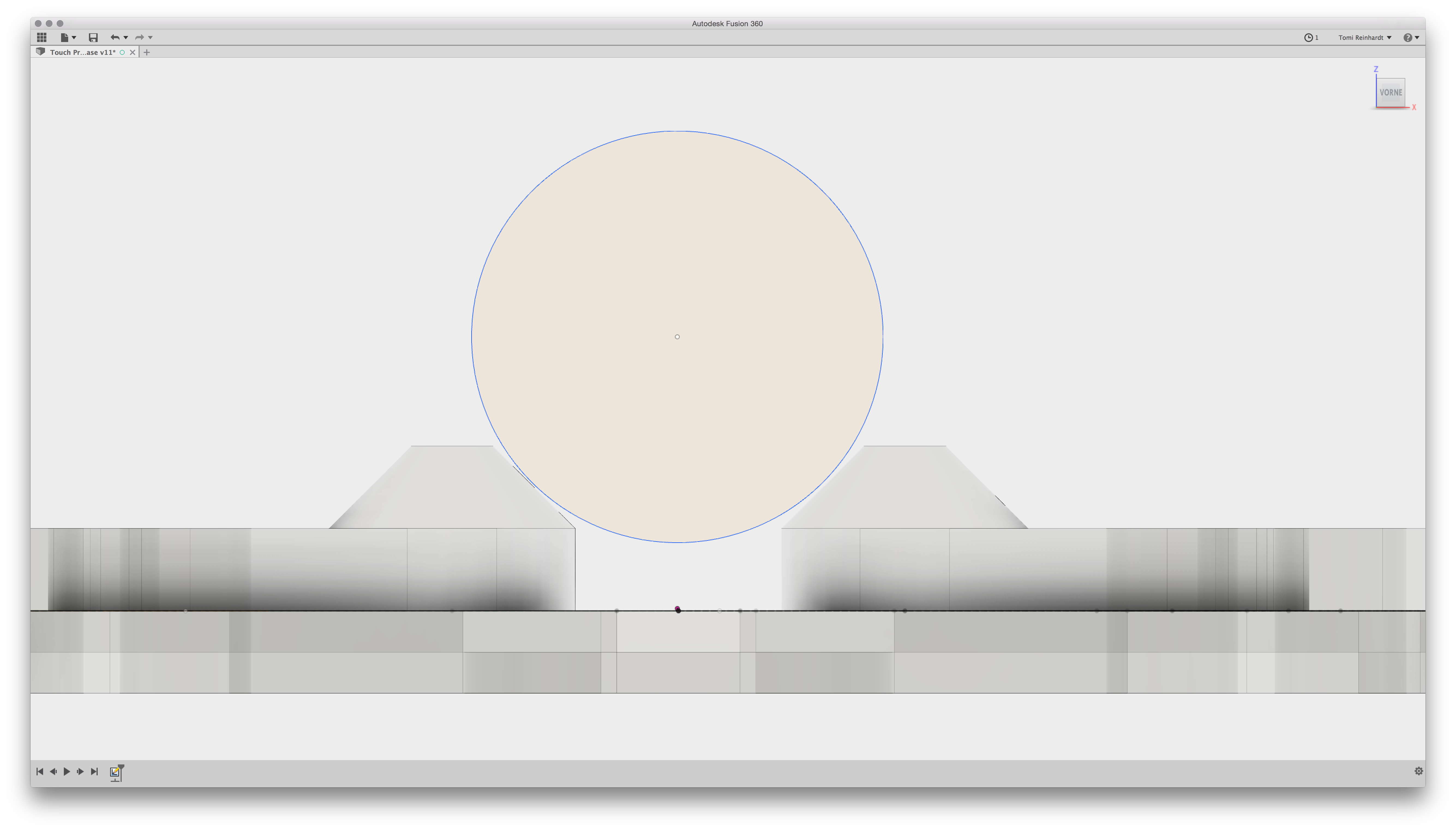
The model and the G-Code for the milling machine was generated in Fusion 360. I milled it directly glued on the «kind of» wooden base – if the glue’s cured correctly, the part shouldn’t break.
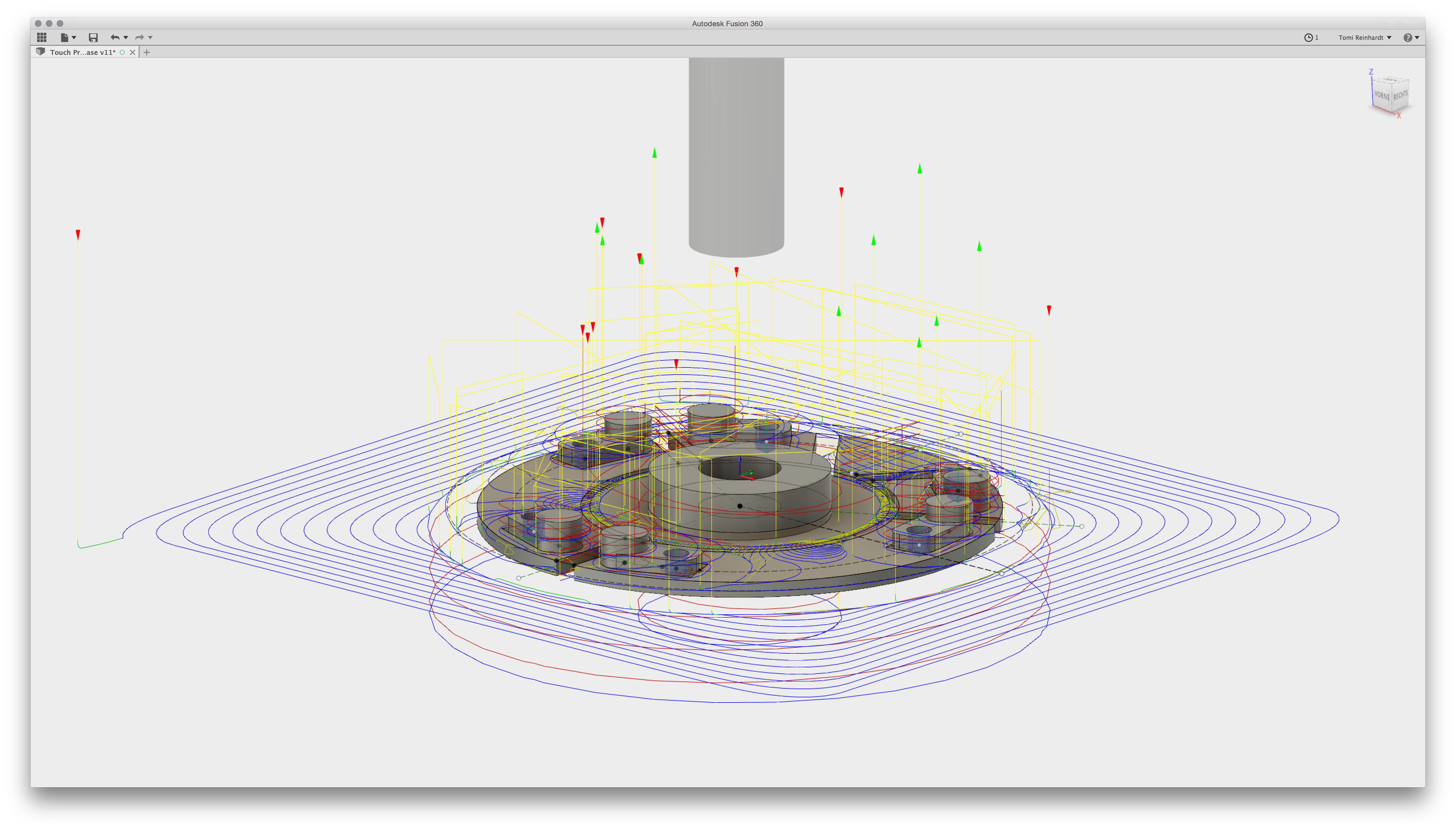
This way I got two basic advantages: probably the milling machine is more accurate than glueing some stainless-steel-bearing-balls and it’s really easier to plan such an assembly with gaps being bridget with some rods:
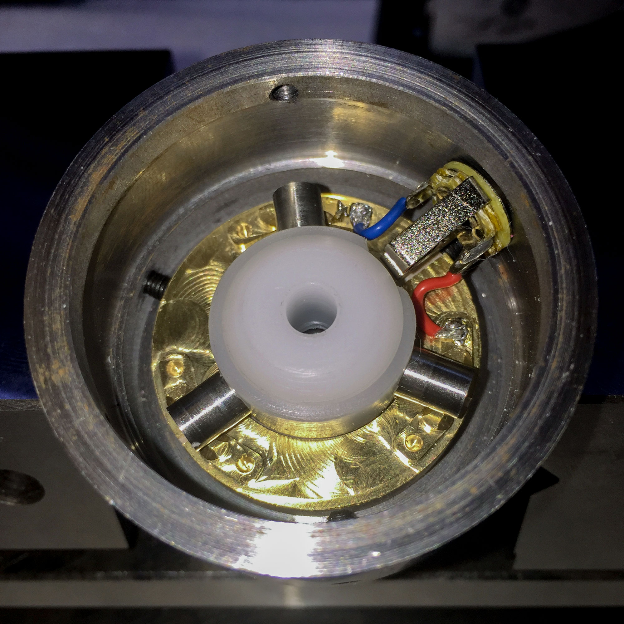
So there we go! The finished assembly mounted in the base and wired on some standard 3.5 mm headphone jack which leads to the CNC-machine:
First test: the probe works fine. Don’t know yet about the accuracy, I need to dial it in and do some calibrations first. But I’m already satisfied, that the concept works and that the probe tip doesn’t get crushed in the first tries…
Additional edit after setup and adjustment
The adjustment is very easy to do in the Pathpilot software. With a little patience, it’s possible to get close to some hundrets of milimeters, which is enough accuracy for my daily needs. Here you can see the output while adjusting it:
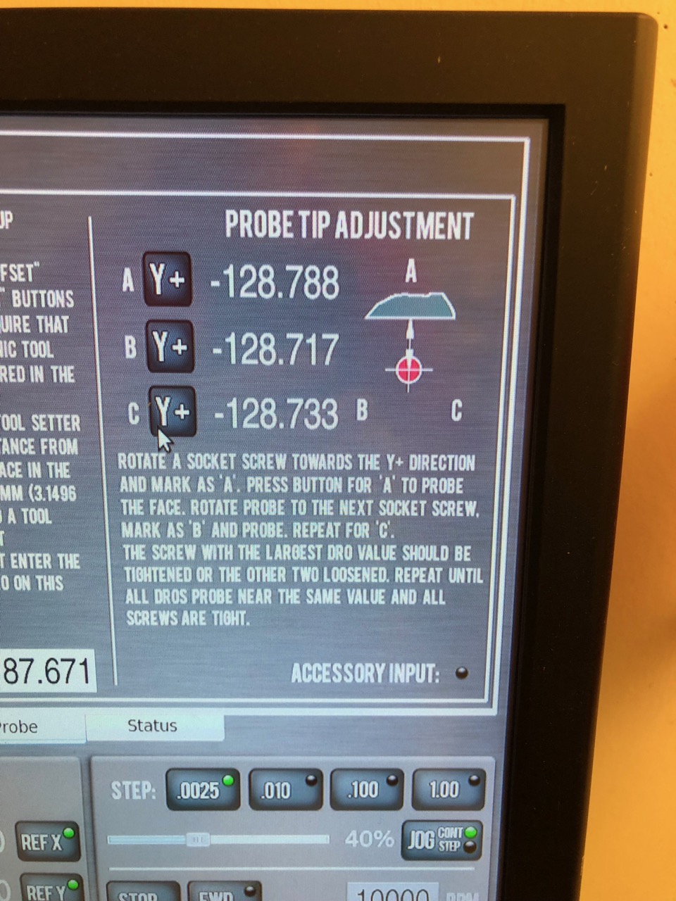
Patience! It lasted until 4/100 mm for me 😉
The usage is simple, but for my person: not as fast as the Haimer. At least for the standard setup – for dialing in prepared stock or holes or such things, this probe will still be my first choice!